Slag blocking system for steel smelting

A technology for iron and steel smelting and filter screen, applied in the field of iron and steel smelting, can solve the problems such as the inability to effectively improve the flow trajectory of molten steel, the uneven flow of molten steel in the tundish, and the inability to reasonably distribute the flow direction of molten steel, so as to achieve a good slag blocking effect and improve the flow trajectory. , the effect of simple structure

Inactive Publication Date: 2016-08-17
CHONGQING YUXI STEEL GRP CO LTD
View PDF0 Cites 2 Cited by
  • Summary
  • Abstract
  • Description
  • Claims
  • Application Information

AI Technical Summary

Problems solved by technology

[0002] In the prior art, in the iron and steel smelting process, due to the uneven flow of molten steel in the tundish, some places are slow and some places are fast, especially there is an inactive molten steel stagnation zone in the bottom area of ​​the tundish, which makes the inclusions float difficulty
In order to fully and effectively utilize the volume of the tundish and promote the floating of inclusions, people usually set up a slag blocking system in the tundish. The traditional slag blocking system is generally a flat wall, and there is no or only one flow steel hole on the wall. The setting is unreasonable. In the actual use process, the flow direction of molten steel cannot be reasonably distributed, and the flow trajectory of molten steel cannot be effectively improved. It is easy to cause surface fluctuations caused by turbulent flow diffusion and slag is involved in the molten steel, and some residues are difficult to be cleanly removed. , it is difficult to meet the production demand

Method used


Image

  • Slag blocking system for steel smelting
  • Slag blocking system for steel smelting

Examples


specific Embodiment approach

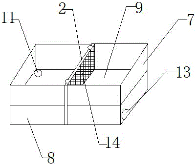
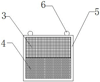
[0017] The specific embodiment: when in use, molten steel is input from the feed port, enters the upper filter layer 7, passes through the upper layer filter screen 3 of the filter screen main body 2, carries out slag blocking, then flows into the lower filter layer 8 from the lower leakage hole 11, passes through The lower layer filter screen 4 is used for the second slag blocking, and finally the molten steel that has been slag blocking is discharged from the discharge port 13. The filter screen main body 2 can be installed and fixed on the middle position of the body from the filter screen fixing slideway, and the present invention The reasonable design of the size and shape of the mesh hole 14 of the upper filter 3 and the lower filter 4 can completely remove the slag distributed in the molten steel, and the slag is blocked twice in the molten steel, so that the slag can be removed more thoroughly , improve the molten steel flow track at the same time, so that the slag bloc...


PUM

PropertyMeasurementUnit
diameteraaaaaaaaaa

Abstract

The invention provides a slag-retaining system for iron and steel smelting, which includes a machine body and a main body of a filter screen, a frame is arranged around the main body of the filter screen, a handle is provided on the frame, an upper filter layer and a lower filter layer of the machine body, and the upper filter layer and the lower filter layer are composed of The interlayers are separated from each other, the upper left corner of the interlayer is provided with a lower drain hole, the middle of the body is provided with a filter screen fixed slideway, the upper right corner of the body is provided with a material inlet, the lower right corner of the body is provided with a discharge port, and the mesh of the upper filter net The shape of the hole is square. Compared with the prior art, the present invention has the following benefits: the reasonable design of the size and shape of the mesh hole of the present invention can completely block the debris distributed in molten steel, and the main body of the filter screen can be removed from the Take it out from the body, clean or replace it, and keep the main body of the filter screen clean. The inner surface and outer surface of the body are each attached with a layer of fireproof and heat-resistant coating, which can increase the service life of the invention. The invention has simple structure, simple operation and convenient cleaning.

Description

technical field [0001] The invention relates to a slag blocking system for iron and steel smelting, which belongs to the technical field of iron and steel smelting. , Background technique [0002] In the prior art, in the iron and steel smelting process, due to the uneven flow of molten steel in the tundish, some places are slow and some places are fast, especially there is an inactive molten steel stagnation zone in the bottom area of ​​the tundish, which makes the inclusions float difficulty. In order to fully and effectively utilize the volume of the tundish and promote the floating of inclusions, people usually set up a slag blocking system in the tundish. The traditional slag blocking system is generally a flat wall, and there is no or only one flow steel hole on the wall. The setting is unreasonable. In the actual use process, the flow direction of molten steel cannot be reasonably distributed, and the flow trajectory of molten steel cannot be effectively improved. I...

Claims


Application Information

Patent Timeline
Patent Type & Authority Applications(China)
IPC IPC(8): B22D43/00
CPCB22D43/004
Inventor 周木火
Owner CHONGQING YUXI STEEL GRP CO LTD
Why Eureka
Try Eureka