
An electrode processing device for an electric discharge forming machine tool and a method for using the same

A technology of forming processing and electrode processing, applied in electric processing equipment, electrode manufacturing, metal processing equipment, etc., can solve the problems of unstable electrode processing quality and poor practicability, and achieve the expansion of comprehensive processing capabilities, good stability, and smooth movement. Effect

Active Publication Date: 2017-11-10
DALIAN UNIV
View PDF3 Cites 0 Cited by
  • Summary
  • Abstract
  • Description
  • Claims
  • Application Information

AI Technical Summary

Problems solved by technology

[0010] 1. It can ensure the constant moving speed and stable movement of the electrode wire, and overcome the shortcomings of the prior art centerline electrode grinding device, which restricts the unstable electrode processing quality and poor practicability due to the change of the electrode wire moving speed;

Method used


Image

  • An electrode processing device for an electric discharge forming machine tool and a method for using the same
  • An electrode processing device for an electric discharge forming machine tool and a method for using the same
  • An electrode processing device for an electric discharge forming machine tool and a method for using the same

Examples


Embodiment 1

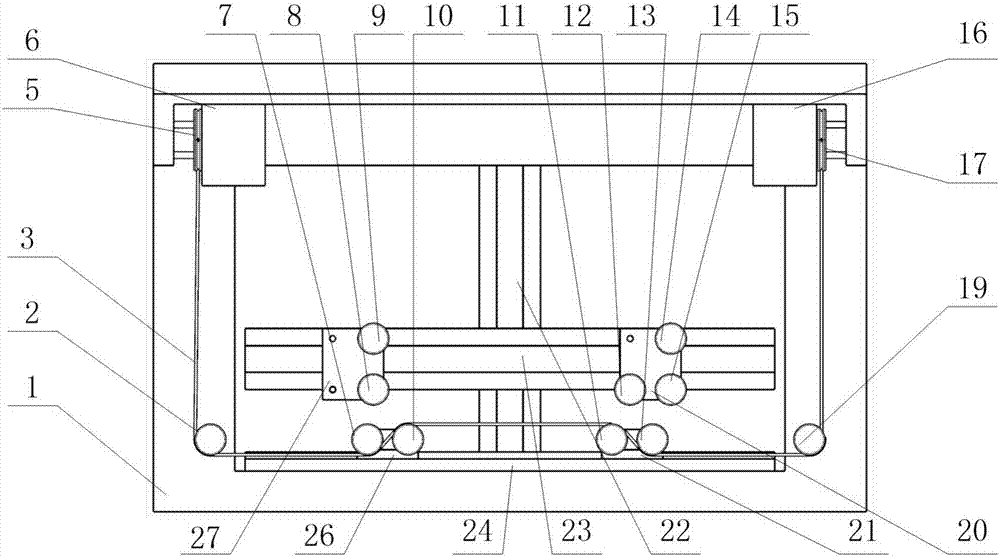
[0084] Example 1: Grinding Cylindrical Electrode

[0085] S1. Clamp the body 1 on the magnetic chuck of the machine tool and conduct the power supply with the magnetic chuck end;

[0086] S2. Install the electrode wire 3: Lead the electrode wire 3 from the wire feeding wheel 16, through the resistance wheel 17, the front side of the guide wheel G13, the back side of the guide wheel E11, the back side of the guide wheel D10, and the front side of the guide wheel A7 , guide wheel A2, guide wheel B4 and driving wheel 5 enter the receiving wheel 6; as figure 2 shown.

[0087] S3. Adjust the distance between the slider B21 and the slider D26 according to the size of the electrode to be processed, so that the electrode wire 3 moves at a constant speed in a single line;

[0088] S4. Start the machine tool to set the coordinate system, set the program through the machine operation panel, start processing, and the electrode to be processed rotates at a constant speed. The movement ...

Embodiment 2

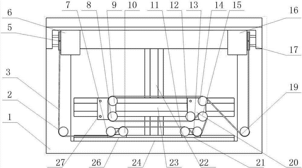
[0090] Example 2: Cutting thin-sheet electrodes

[0091] S1. Clamp the body 1 on the magnetic chuck on the machine tool and conduct the power supply with the magnetic chuck end;

[0092] S2. Install the electrode wire 3: Lead the electrode wire 3 from the wire feeding wheel 16, pass through the resistance wheel 17, the guide wheel C18, the guide wheel D19, the back side of the guide wheel H14, the back side of the guide wheel C9, and the front of the guide wheel B8 side, front side of guide wheel F12, back side of guide wheel I15, front side of guide wheel G13, back side of guide wheel E11, back side of guide wheel D10, front side of guide wheel A7, guide wheel A2, guide wheel B4 and driving wheel 5 enter the receiving wheel 6; as image 3 shown.

[0093] S3. Adjust the distance between the slider B21 and the slider D26, the slider A20 and the slider E27, the slider C25 and the sliding guide rail C24 according to the size of the electrode to be processed, so that the electro...


PUM


Abstract

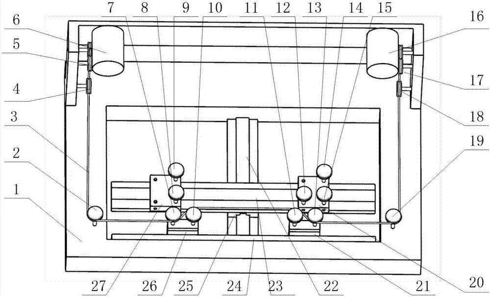
The invention discloses an electrode machining device of an electric spark forming machining tool and a use method of the device. The device comprises a body, a wire winding wheel, a wire unwinding wheel, a guide rail, guide rollers, a guiding wheel, a driving wheel, a resistance wheel, sliding guide rails and sliders. The body is fixed to a magnetic suction cup. The wire winding wheel, the wire unwinding wheel, the sliding guide rail, the driving wheel, the resistance wheel and the guiding wheel are fixed to the body. The functions of wire winding, wire unwinding, driving and constant tension force are achieved by means of the wire winding wheel, the wire unwinding wheel, the driving wheel and the resistance wheel respectively, it is guaranteed that electrode wire moving speed and tension force are constant and can be adjusted continuously, the structure is compact, and stability is good. By the adoption of design of a five-slider three-sliding-guide-rail combined module, different sliders are selected to participate in electrode wire moving to achieve single-wire and double-wire machining modes, and electrodes in different sizes can be machined by adjusting the positions of the sliders to adjust the interval of the guide rollers and the distance of electrode wires.

Description

technical field [0001] The invention belongs to the field of precision electric discharge machining, and in particular relates to an electrode processing device of an electric discharge forming machine tool. Background technique [0002] With the development of science and technology, various mechanical parts are becoming increasingly miniaturized, complex, and lightweight, thus proposing a large number of manufacturing requirements for parts with tiny features (such as holes, slots, slots, and complex tiny three-dimensional cavities, etc.). This puts forward higher requirements for micromachining technology, and at the same time promotes the development of conventional machine tools to the EDM capability of large-scale parts microstructure. Due to the characteristics of non-contact, no macro cutting force, and wide application range of materials, electric machining technology has incomparable advantages in the field of processing difficult-to-machine material parts and smal...

Claims


Application Information

Patent Timeline
Patent Type & Authority Patents(China)
IPC IPC(8): B23H7/22
CPCB23H7/22
Inventor 王元刚李晓鹏吴蒙华王珍
Owner DALIAN UNIV
Learn More