
Wing load applying device

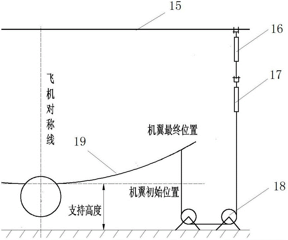
A loading device and load technology, which is applied to ground equipment, aircraft parts, transportation and packaging, etc., can solve the problems of uncoordinated load loading, overload protection, and low control accuracy, and achieve the effect of improving loading control accuracy

Active Publication Date: 2016-08-17
CHINA AIRPLANT STRENGTH RES INST
View PDF5 Cites 5 Cited by
  • Summary
  • Abstract
  • Description
  • Claims
  • Application Information

AI Technical Summary

Problems solved by technology

The two actuators in this loading method are soft in series, and the actuators can rotate freely, so it is difficult to lift and install; It leads to overload protection and brings test risks; thirdly, the two actuators are controlled by a control module, the control accuracy is low, the loading speed is slow, it is not easy to synchronize with other loading equipment, and the load loading is not coordinated

Method used


Image

  • Wing load applying device
  • Wing load applying device
  • Wing load applying device

Examples


Embodiment Construction

[0028] In order to make the objectives, technical solutions and advantages of the present invention clearer, the technical solutions in the embodiments of the present invention will be described in more detail below in conjunction with the drawings in the embodiments of the present invention. In the drawings, the same or similar reference numerals denote the same or similar elements or elements having the same or similar functions throughout. The described embodiments are some, but not all, embodiments of the invention. The embodiments described below by referring to the figures are exemplary and are intended to explain the present invention and should not be construed as limiting the present invention. Based on the embodiments of the present invention, all other embodiments obtained by persons of ordinary skill in the art without creative efforts fall within the protection scope of the present invention. Embodiments of the present invention will be described in detail below ...


PUM


Abstract

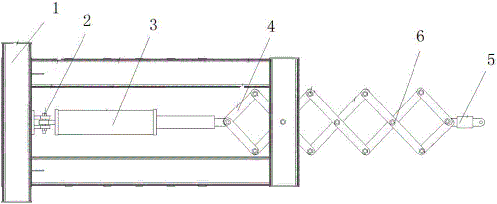
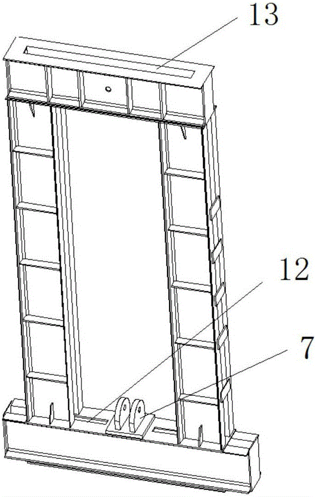
The invention discloses a wing load applying device, belongs to the technical field of airplane structure tests, and is applicable to application of a load to the surface of a wing under a condition of large deformation. The wing load applying device comprises a framework, a connection bolt, an actuator cylinder, a telescopic device, a load sensor and pulling plate bolts, wherein a double-lug joint is arranged at the bottom of the framework; a bottom end single lug joint and a top end single lug joint are arranged at two ends of the actuator cylinder; the framework and the actuator cylinder penetrate through the bottom end single lug joint and the top end single lug joint so as to be movably connected through connection bolts; the telescopic device and the actuator cylinder penetrate through the top end single lug joint through the pulling plate bolts so as to be movably connected; the telescopic device penetrates through the framework and is movably connected with the load sensor. According to the load applying device, the actuator cylinder can be retracted and shortened to apply a downward stretching load to the lower wing surface of the wing and also extend to meet the upward large deformation of the wing; meanwhile, the wing load applying device is easy and convenient to manufacture and mount, low in manufacturing cost and convenient for load application control; the load application control precision is improved, and generation of an impact load is effectively avoided.

Description

technical field [0001] The invention belongs to the technical field of aircraft structure testing, and in particular relates to a wing load loading device. Background technique [0002] In some working conditions of the ground test of the aircraft structure, the upper surface of the wing is loaded with an upward load, the lower surface of the wing is loaded with a downward load, and the wing deforms upward. Under this deformation condition, the loading device on the lower airfoil needs to elongate upward with the increase of the load. The maximum stroke of the existing loading actuator is 2500 mm. When the deformation exceeds 2500 mm, the load on the lower airfoil cannot be loaded. [0003] The loading technology of the lower wing surface under the condition of large deformation of the wing is a difficult point in the ground test of the aircraft. At present, there is no loading device that can easily load the load. Usually, the method of double actuators in series and revers...

Claims


Application Information

Patent Timeline
IPC IPC(8): B64F5/00
Inventor 臧伟锋陈安张侃张海英苏少普
Owner CHINA AIRPLANT STRENGTH RES INST
Learn More