Traction power system for elevator

A power system and traction technology, applied in the field of elevators, can solve the problems of short service life of parts, high frequency of maintenance, high frequency of replacement of wearing parts, etc., and achieve the effect of improving stability and convenient operation

Active Publication Date: 2016-08-17
ISAAC ELECVATOR CO LTD
View PDF6 Cites 5 Cited by
  • Summary
  • Abstract
  • Description
  • Claims
  • Application Information

AI Technical Summary

Problems solved by technology

As a special equipment, the safety of the elevator is directly related to the life safety of passengers. Therefore, the requirements for elevator repair and maintenance are high, that is, the frequency of maintenance is high, the service life of parts is short, and the replacement of vulnerable parts High frequency
And the elevator needs to lock the car and the counterweight during the maintenance process, so as to facilitate the loosening of the traction wire rope, and realize the inspection or replacement of the guide wheels of each component. In the elevator maintenance of the prior art, the guide wheels After the maintenance or replacement is completed, when the traction wire rope is reset, there is a risk of misalignment between the traction wire rope and the guide wheel, that is, the traction wire rope slips from the guide wheel, thereby causing the shaft of the traction wire rope and the guide wheel to be stuck, or As a result, the rotating shaft of the guide wheel is constantly rubbed against the traction wire rope, resulting in premature damage to both parts

Method used


Image

  • Traction power system for elevator
  • Traction power system for elevator
  • Traction power system for elevator

Examples


Embodiment Construction

[0023] The present invention will be further described below with reference to the accompanying drawings and specific embodiments.

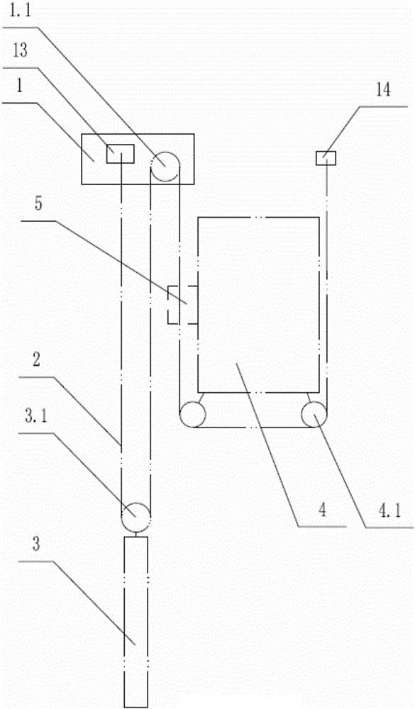
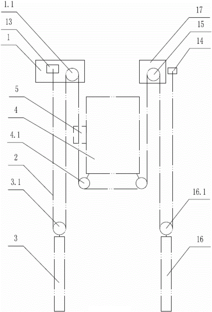
[0024] The invention provides a traction power system for an elevator, which includes a traction machine 1 installed in the elevator shaft, a traction wire rope 2 and a counterweight 3 arranged under the traction machine 1, and is characterized in that: One end of the wire rope 2 is fixed to the casing of the traction machine 1, the other end of the traction wire rope 2 is fixed to the inner wall of the elevator shaft, and the middle part of the traction wire rope 2 encircles the counterweight wheel 3.1, traction The driving wheel 1.1 on the machine 1 and the guide wheel 4.1 arranged at the bottom of the car 4, a pre-tensioning mechanism 5 is provided on the outer wall of the car 4, which is used to draw the wire rope when the counterweight 3 and the car 4 are not aligned. 2 Make the traction wire rope 2 tight when applying force. There are mult...


PUM


Abstract

The invention discloses a traction power system for an elevator. The traction power system comprises a traction machine, a traction steel wire rope and a counterweight block arranged below the traction machine. The traction power system is characterized in that one end of the traction steel wire rope is fixed with a housing of the traction machine, wherein the other end of the traction steel wire rope is fixed with the inner wall of an elevator hoistway; a pre-tightening mechanism is arranged on the outer side wall of the car; a ring-shaped groove is formed in the outer circumferential wall of a guide wheel; at least three clamping slots which are formed in an internally tangent manner in the radial direction of the guide wheel are formed in the groove bottom of the ring-shaped groove; all clamping slots are uniformly distributed in the circumferential direction of the guide wheel; clamping blocks are arranged in the clamping slots; and the clamping blocks are detachably connected with the clamping slots. According to the traction power system for the elevator provided by the invention, in an elevator maintenance process, a car and the counterweight block can guarantee that the traction steel wire rope does not slip from the guide wheel while not applying acting force to the traction steel wire rope, so that the risk that the traction steel wire rope slips from the guide wheel is avoided.

Description

technical field [0001] The invention relates to the technical field of elevators, in particular to a traction power system for elevators. Background technique [0002] The lifting process of the elevator is to wind the driving wheel of the traction machine, the guide wheel of the car and the counterweight wheel of the counterweight in sequence through the traction wire rope, so as to drive the movement of the car through the friction between the driving wheel and the traction wire rope. lift. As a special equipment, the safety of the elevator is directly related to the life safety of passengers. Therefore, the requirements for elevator repair and maintenance are high, that is, the frequency of maintenance is high, the service life of parts is short, and the replacement of vulnerable parts High frequency. And the elevator needs to lock the car and the counterweight during the maintenance process, so as to facilitate the loosening of the traction wire rope, and realize the i...

Claims


Application Information

Patent Timeline
IPC IPC(8): B66B11/04B66B7/08
CPCB66B7/08B66B11/04
Inventor 袁陆峰曹诗晴
Owner ISAAC ELECVATOR CO LTD
Why Eureka
Try Eureka