A Method for Reducing Negative Bending Moment of T-Frame Bridge

A negative bending moment, cantilever end technology, applied in bridges, bridge construction, erection/assembly of bridges, etc., can solve the problems of empty, uneconomical, and unsatisfactory bridge alignment requirements for side pier supports, and achieves the prevention of emptying and Drop, improve driving comfort, solve the effect of sagging deformation

Active Publication Date: 2017-12-12
CHINA RAILWAY DESIGN GRP CO LTD
View PDF4 Cites 0 Cited by
  • Summary
  • Abstract
  • Description
  • Claims
  • Application Information

AI Technical Summary

Problems solved by technology

If no measures are taken, the excessive negative bending moment of the main girder at the main pier will result in a large amount of steel used and a large beam section, which is uneconomical, and the excessive sagging deformation does not meet the requirements of the bridge alignment, which also affects the driving comfort
In addition, it will also cause the reaction force of the side pier to be too small, causing the support of the side pier to be empty or even fall.

Method used


Image

  • A Method for Reducing Negative Bending Moment of T-Frame Bridge
  • A Method for Reducing Negative Bending Moment of T-Frame Bridge
  • A Method for Reducing Negative Bending Moment of T-Frame Bridge

Examples


Embodiment Construction

[0012] In order to further understand the invention content, characteristics and effects of the present invention, the following examples are given, and detailed descriptions are as follows in conjunction with the accompanying drawings:

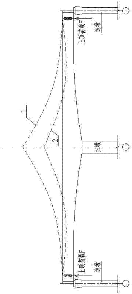
[0013] The concept of the present invention is: after the construction of the cantilever end of the main girder of the T-structure bridge is completed or the construction of the swivel body is in place, the top load is applied to the cantilever end of the main girder to make it reach the predetermined design elevation and make it meet the requirements of the bridge alignment. In this way, the excessive negative bending moment generated by the main beam at the main pier is eliminated and the reaction force of the side pier support is appropriately increased.

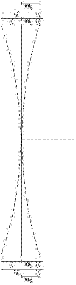
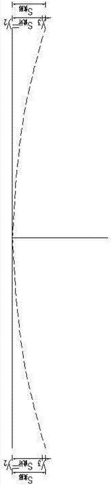
[0014] Concrete scheme of the present invention please refer to Figure 1 ~ Figure 3 , a method for reducing the negative bending moment of a T-structure bridge. In the design stage, the...


PUM


Abstract

The invention discloses a method for reducing the negative bending moment of a T-type rigid bridge. The method comprises the steps that in the design stage, an upward jacking load design value is calculated according to a counter force design value of side pier supports and a set reducing value of the negative bending moment of a main beam arranged at a main pier, and an upward jacking displacement design value sdesign is calculated according to the upward jacking load design value; in the construction stage, the upward jacking displacement design value sdesign is corrected according to a construction error of the height of the cantilever end of the T-type rigid bridge to obtain an actual upward jacking displacement value sactual, an actual upward jacking load F is determined according to the actual upward jacking displacement value sactual, then a jack is adopted to apply the actual upward jacking load F at the cantilever end of the T-type rigid bridge, and the T-type rigid bridge is made to meet the requirement of a bridge line. According to the method, the negative bending moment of the main beam arranged at the bridge pier is reduced, stress is reasonable, and materials are saved; the counter force of the side pier supports is appropriately increased, and disengaging and dropping of the side pier supports can be effectively prevented; main beam drooping deformation generated during construction is effectively solved, and the driving comfort is improved.

Description

technical field [0001] The invention relates to a construction method of a T-structure bridge, in particular to a method for reducing negative bending moments of a T-structure bridge. Background technique [0002] T-frame bridge is a type of rigid-frame bridge, which has the characteristics of cantilever force, and cantilever construction method can be used, that is, the upper beam body of the structure is constructed segment by segment from the top of the main pier to both sides by using a balanced cantilever construction method to form a " T”-shaped double cantilever structure, and then the construction of the bridge closing section. The T-frame bridge can also use the construction support to carry out the construction of the cantilever of the main beam. [0003] After the cantilever method construction of the T-structure bridge or the removal of the construction support of the main beam, the main beam at the main pier will produce excessive negative bending moment, and t...

Claims


Application Information

Patent Timeline
Patent Type & Authority Patents(China)
IPC IPC(8): E01D21/00E01D2/00
CPCE01D2/00E01D21/00
Inventor 田山坡刘涛宋顺心侯春辉
Owner CHINA RAILWAY DESIGN GRP CO LTD
Why Eureka
Try Eureka