A Method for Longitudinal Connection of the Main Girder at the Continuation of the Bridge Deck of a Steel-Concrete Composite Bridge

A technology of longitudinal connection and steel girders, which is applied in the direction of bridges, bridge construction, bridge parts, etc., can solve the problems of complex structure and aggravated transverse cracking of bridge deck pavement, and achieve simple operation, reduced deformation and deformation of concrete slabs, and energy saving cost effect

Active Publication Date: 2021-01-05
SHAOXING UNIVERSITY
View PDF7 Cites 0 Cited by
  • Summary
  • Abstract
  • Description
  • Claims
  • Application Information

AI Technical Summary

Problems solved by technology

Rigid connection at the continuous part of the bridge deck belongs to the statically indeterminate structure, the structure is relatively complex, and due to the existence of the negative bending moment of the fulcrum at the continuous point, the concrete near the fulcrum bears a large tensile force. In actual engineering, the concrete slab above the fulcrum is often with Crack work, after the bridge deck pavement and structure are jointly stressed, is further aggravated by various factors such as repeated rolling by heavy vehicles, temperature effects of the structure, rainwater penetration, rusting of steel bars, and shrinkage and creep of concrete. Transverse cracks occur in the pavement layer of the bridge deck, which has an adverse effect on driving

Method used


Image

  • A Method for Longitudinal Connection of the Main Girder at the Continuation of the Bridge Deck of a Steel-Concrete Composite Bridge
  • A Method for Longitudinal Connection of the Main Girder at the Continuation of the Bridge Deck of a Steel-Concrete Composite Bridge
  • A Method for Longitudinal Connection of the Main Girder at the Continuation of the Bridge Deck of a Steel-Concrete Composite Bridge

Examples


Embodiment Construction

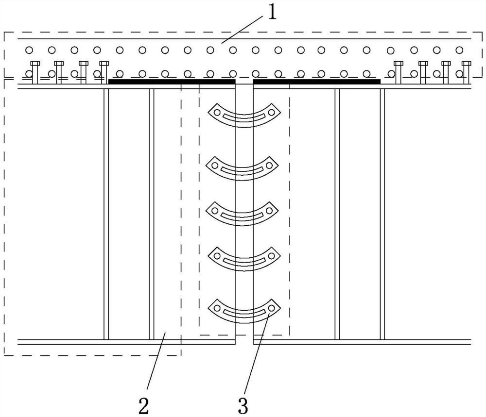
[0026] Please refer to the attached figure 1 to attach Figure 5 As shown, the present invention is a method for longitudinally connecting the main girder at the continuous part of the deck of a steel-concrete composite bridge, comprising the following process steps:

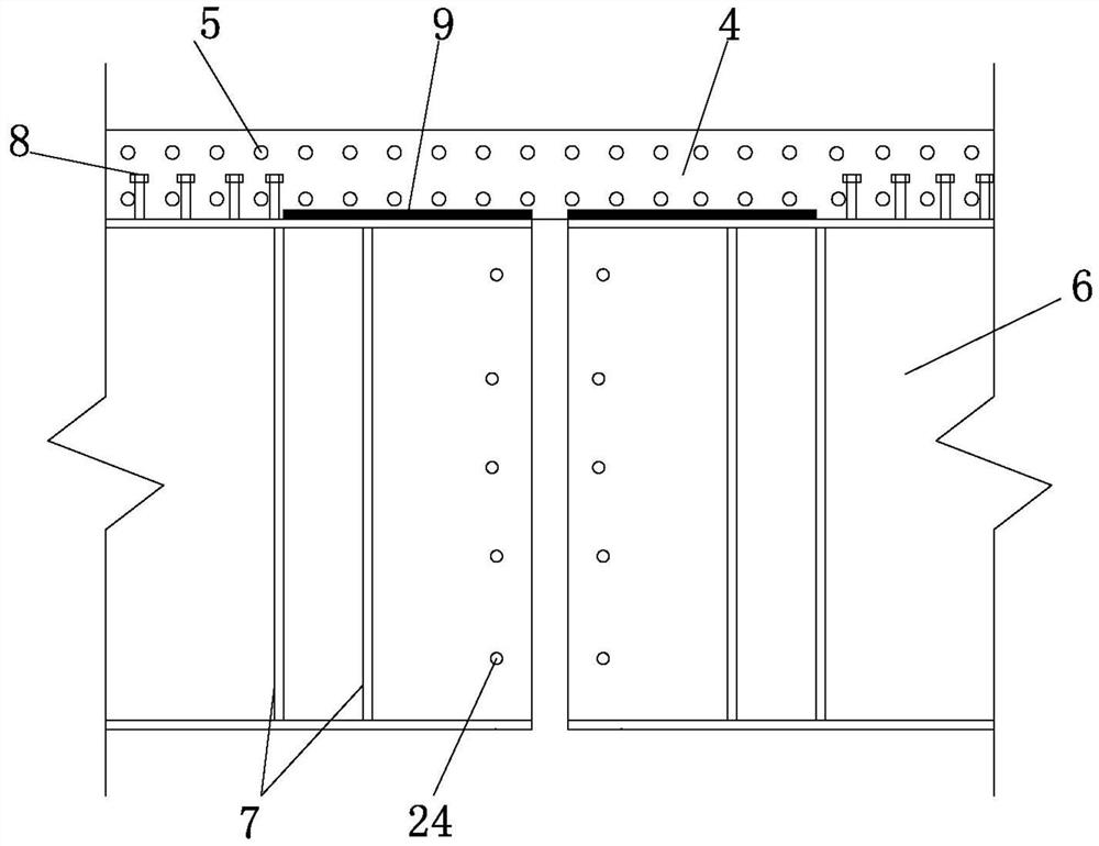
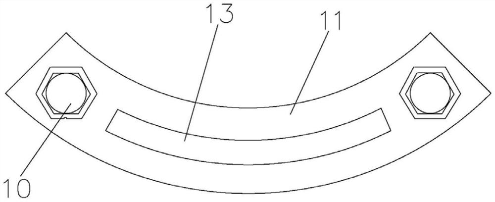
[0027] 1), in the factory, according to the design drawings, the section steel 6, the stiffener 7 and the shear key 8 are welded or bolted according to the design requirements to make the steel girder 2; a reserved bolt hole is set at the corresponding position of the web of the section steel 6, and the For the arrangement of U-shaped steel hinge 3;

[0028] 2), transport the processed steel girder 6 to the construction site, and fix it on the temporary support, then arrange the rubber pad 9 at the end of the steel girder, lay the formwork, pour the concrete bridge deck 1, and perform maintenance. After the strength of bridge deck 1 meets the specification requirements, remove the formwork;

[0029] 3), use t...


PUM


Abstract

The invention relates to a method for longitudinally connecting a main beam at a continuous position of a steel-concrete composite bridge deck, which comprises the following steps: 1) welding or bolting a section steel, a stiffening rib and a shear key according to design requirements in a factory according to design drawings to produce a steel beam; the corresponding position of the web of the section steel is provided with a reserved bolt hole for arranging the U-shaped steel hinge; 2) transporting the processed steel beam to the construction site, fixing it on the temporary support, arranging rubber cushion at the end of the steel beam, laying formwork, pouring concrete bridge deck and curing, and removing the formwork when the strength of concrete bridge deck reaches the requirements of the specifications; 3) connecting the two side steel beams with the prefabricated U-shaped steel hinge standard parts; 4) removing the temporary support, and landing the steel beam on the permanentsupport to complete the connecting structure at the continuous position of the main beam of the steel-concrete composite continuous beam bridge. The connecting method of the invention has the advantages of firm structure, rapid construction, cost saving and the like.

Description

【Technical field】 [0001] The invention relates to a bridge connection structure and a construction method thereof, in particular to a method for longitudinally connecting main girders at continuous bridge decks of steel-concrete composite bridges, and belongs to the technical field of bridge engineering. 【Background technique】 [0002] In existing prefabricated steel-concrete composite girder bridges, the connection mode of the main girder at the continuous part of the bridge deck mainly adopts rigid connection, while the upper concrete bridge deck adopts the method of integral cast-in-place. Rigid connection at the continuous part of the bridge deck belongs to the statically indeterminate structure, the structure is relatively complex, and due to the existence of the negative bending moment of the fulcrum at the continuous point, the concrete near the fulcrum bears a large tensile force. In actual engineering, the concrete slab above the fulcrum is often with Crack work, af...

Claims


Application Information

Patent Timeline
Patent Type & Authority Patents(China)
IPC IPC(8): E01D19/00E01D19/12E01D21/00
CPCE01D19/00E01D19/125E01D21/00
Inventor 王立超何余良王栋威肖景平
Owner SHAOXING UNIVERSITY
Why Eureka
Try Eureka