Single-tower self-anchored suspension bridge structure without lower cross beam and construction method of single-tower self-anchored suspension bridge structure

A self-anchored suspension bridge and construction method technology, applied in suspension bridges, bridge forms, bridges, etc., can solve the problems of reducing the aesthetics of a single-pylon self-anchored suspension bridge, limited clearance under the bridge, insufficient permeability, etc. Transparency and aesthetics, simple structure of the bridge tower, guaranteeing the effect of safety and economy

Active Publication Date: 2022-07-08
CCCC SECOND HARBOR ENG +1
View PDF7 Cites 0 Cited by
  • Summary
  • Abstract
  • Description
  • Claims
  • Application Information

AI Technical Summary

Problems solved by technology

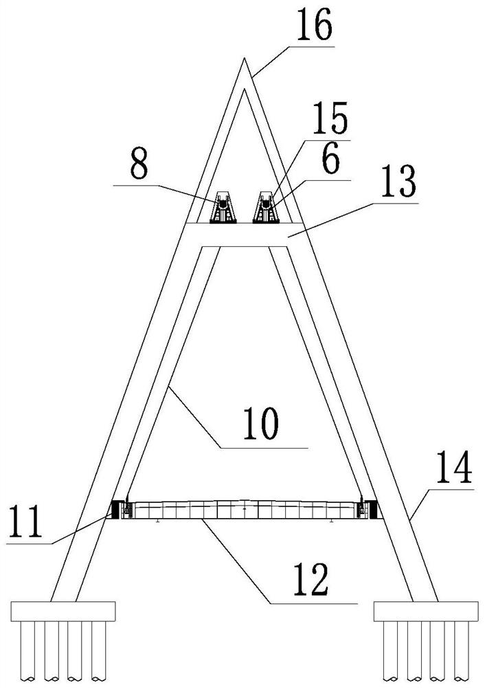
[0003] The stiffened girder section of the traditional single-tower self-anchored suspension bridge tower area is usually supported on the lower beam of the bridge tower. The cross-sectional size of the stiffened beam section in the tower area or measures such as pouring concrete inside the stiffened beam section at the bridge tower position are used to ensure that the stiffened beam section at the bridge tower position is always in a safe and stable state; on the other hand, the single tower is self-anchored Because the lower beam of the suspension bridge needs to bear the comprehensive effect of the vehicle load, the self-weight of the stiffened beam section and its own weight, its cross-sectional size is usually large, resulting in limited clearance and insufficient permeability under the bridge, which greatly reduces the self-weight of the single tower. Aesthetics of Anchored Suspension Bridge

Method used


Image

  • Single-tower self-anchored suspension bridge structure without lower cross beam and construction method of single-tower self-anchored suspension bridge structure
  • Single-tower self-anchored suspension bridge structure without lower cross beam and construction method of single-tower self-anchored suspension bridge structure

Examples


Embodiment Construction

[0033] The present invention will be further described in detail below with reference to the accompanying drawings, so that those skilled in the art can implement it with reference to the description.

[0034] It should be noted that the experimental methods described in the following embodiments are conventional methods unless otherwise specified, and the reagents and materials can be obtained from commercial sources unless otherwise specified; in the description of the present invention, The terms "landscape", "portrait", "top", "bottom", "front", "rear", "left", "right", "vertical", "horizontal", "top", "bottom", The orientation or positional relationship indicated by "inside" and "outside" is based on the orientation or positional relationship shown in the accompanying drawings, which is only for the convenience of describing the present invention and simplifying the description, and does not indicate or imply that the indicated device or element must have The particular o...


PUM


Abstract

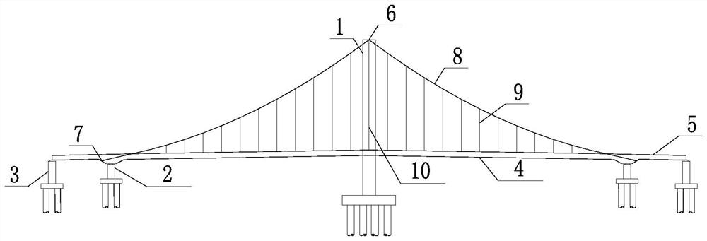
The invention discloses a single-tower self-anchored suspension bridge structure without a lower cross beam and a construction method thereof, and the suspension bridge structure comprises a plurality of pier columns which are arranged at intervals along the length direction of a bridge; the stiffening beam sections are continuously arranged in the length direction of the bridge and supported on the pier columns; the bridge tower is located in the middle of the bridge, and the bridge tower comprises two tower columns which are symmetrically arranged; the upper cross beam is positioned at the top of the bridge tower; the main cable is supported on the saddle on the upper cross beam, and two ends of the main cable are respectively anchored at two ends of the bridge; wherein the stiffening beam section located at the bridge tower is fixed between the two tower columns, and the two ends of the stiffening beam section are connected with the upper cross beams above through cross beam slings respectively. The bridge tower structure without the lower cross beam is adopted, the cross beam slings are additionally arranged in a matched mode to support and stabilize the stiffening beams in the bridge tower area, the hogging moment of the stiffening beams in the bridge tower area is greatly reduced, the permeability and attractiveness of the whole bridge structure are enhanced, and the construction efficiency is improved while the safety and stability of the bridge are guaranteed.

Description

technical field [0001] The invention relates to the technical field of suspension bridge construction. More specifically, the present invention relates to a single-tower self-anchored suspension bridge structure without a lower beam and a construction method thereof. Background technique [0002] In recent years, with the continuous development of new bridge structure materials, new construction technology and new equipment, the construction technology of suspension bridges has developed rapidly, and great breakthroughs have also been made in the span of the main span. Among them, the single-pylon self-anchored suspension bridge has the advantages of beautiful appearance, economy, light structure and strong adaptability because its main cable is anchored on its own stiffened beam section, so it does not need a huge anchor structure, and has the advantages of beautiful appearance, economy, light structure and strong adaptability. widely used. [0003] The stiffening beam se...

Claims


Application Information

Patent Timeline
Patent Type & Authority Applications(China)
IPC IPC(8): E01D21/00E01D19/14E01D19/16E01D11/02
CPCE01D21/00E01D19/14E01D19/16E01D11/02Y02E10/728Y02E10/72
Inventor 代百华黄灿朱金柱郑建新朱浩胡钦侠孙南昌周浩王永威陈圆周仁忠黄甘乐董剑李杰刘洋
Owner CCCC SECOND HARBOR ENG
Why Eureka
Try Eureka