Irrigation channel with ecological pools

A technology for ecological pools and channels, applied in irrigation pipelines, applications, buildings, etc., can solve problems such as non-conformity, difficult aquatic plants, and heavy dredging and dredging work, achieving slow water flow, suitable water temperature, and reducing dredging and dredging work. amount of effect

Active Publication Date: 2016-08-17
HOHAI UNIV
View PDF6 Cites 5 Cited by
  • Summary
  • Abstract
  • Description
  • Claims
  • Application Information

AI Technical Summary

Problems solved by technology

Generally, there are the following problems: 1. The bottom of the irrigation channel is flush, the water depth is basically the same, the flow rate is fast, and it is difficult to grow aquatic plants, making it difficult for aquatic animals such as fish and shrimp to survive in the channel; 2. The traditional channel is a hardened channel, and the length Longer, when the temperature is high in summer, after each irrigation ends and the channel recedes, the bottom of the channel dries up quickly, and aquatic animals and plants will die in large numbers due to lack of water; For dredging work, the dredging workload of channels in plain areas is often large; 4. With the development of society and economy, landscaping of water conservancy projects has also received attention, while traditional channels are mainly lined with concrete, and aquatic plants are difficult to grow. It does not reflect the landscape value of the channel; 5. The traditional lining channel has no function of purifying water quality, and the temperature of the water body tends to rise when the summer is high temperature, which is not conducive to the survival of aquatic organisms; 6. The traditional channel is not suitable for water delivery period and after water delivery The survival of aquatic animals and plants destroys aquatic biodiversity and does not conform to the concept of ecological civilization construction in our country

Method used


Image

  • Irrigation channel with ecological pools
  • Irrigation channel with ecological pools
  • Irrigation channel with ecological pools

Examples


Embodiment Construction

[0027] The technical solutions in the present invention will be clearly and completely described below in conjunction with the accompanying drawings in the embodiments of the present invention. The following examples are only used to illustrate the technical solution of the present invention more clearly, but not to limit the protection scope of the present invention.

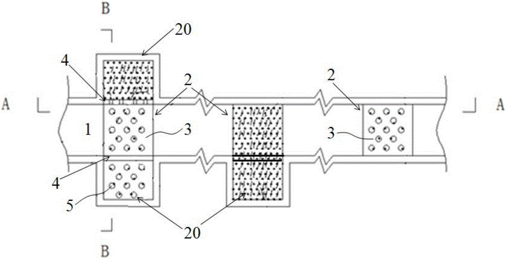
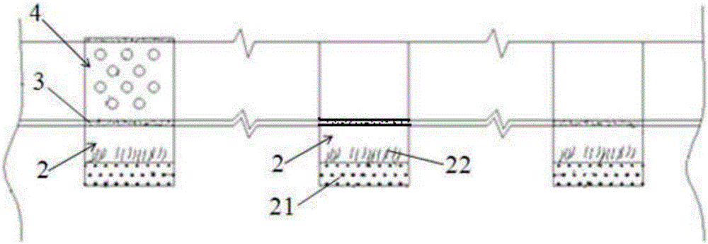
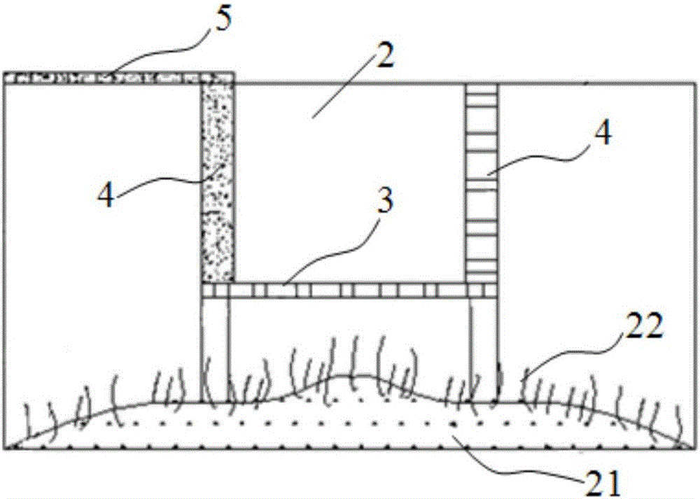
[0028] Such as Figure 1~3 As shown, it is an irrigation channel with an ecological pool, which includes a channel body 1 and a water-storable ecological pool 2 arranged at the bottom of the channel body 1 at equal distances along the longitudinal direction of the channel; A first concrete cover plate 3 with a flush bottom. The first concrete cover plate 3 is provided with a series of through holes. The ecological pool 2 extends to one side or both sides according to the available space on both sides of the channel body 1; the side pool body part 20 extending to one side or both sides and the channel body 1 is...


PUM


Abstract

The invention discloses an irrigation channel with ecological pools. The irrigation channel comprises a channel body and the ecological pools distributed below the channel body at equal intervals. First concrete cover plates flush with the bottom of the channel are arranged on the tops of the ecological pools below the channel body, and a series of through holes are formed in the first concrete cover plates. The ecological pools extend to one side or two sides according to available spaces on the two sides of the channel. Solid second concrete cover plates or second concrete cover plates with through holes are arranged between the lateral pool portions extending to one side or two sides and the channel body, and the second concrete cover plates are flush with an original slope and the top of the channel. The tops of the lateral pool portions are flush with the top of the channel. A third concrete cover plate with a series of through holes is arranged on the tops of the lateral pool portions. The cover plates and the channel body are connected into a whole, and an original section mode of the channel is kept. The irrigation channel improves the biological habitat of a traditional channel, proper ecological space and a shelter site are created, biodiversity is maintained, and the ecological function of the irrigation channel is improved.

Description

technical field [0001] The invention belongs to the technical field of agricultural water conservancy engineering, and in particular relates to an irrigation channel with an ecological pool, which is mainly suitable for plain areas. Background technique [0002] Traditional irrigation channels generally adopt the "three-sided light" lining technology, which often only considers water saving and water delivery efficiency and ignores ecological functions. Generally, there are the following problems: 1. The bottom of the irrigation channel is flush, the water depth is basically the same, the flow rate is fast, and it is difficult to grow aquatic plants, making it difficult for aquatic animals such as fish and shrimp to survive in the channel; 2. The traditional channel is a hardened channel. Longer, when the temperature is high in summer, after each irrigation ends and the channel recedes, the bottom of the channel dries up rapidly, and aquatic animals and plants will die in la...

Claims


Application Information

Patent Timeline
Patent Type & Authority Applications(China)
IPC IPC(8): E02B13/00
CPCE02B13/00
Inventor 陈丹李雪纯陈睿东毕利东毕博汤树海张娣刘辉
Owner HOHAI UNIV
Why Eureka
Try Eureka