A fiber optic gyroscope frequency stabilization device and frequency stabilization method

A fiber optic gyroscope and frequency stabilization technology, applied in the field of inertial measurement, can solve problems such as hindering the development of high-precision fiber optic gyroscopes, and the long-term drift of laser light source frequency cannot be solved, so as to reduce noise sources and system space volume and improve main performance. Metrics, the effect of suppressing jitter and wander

Active Publication Date: 2018-10-09
BEIJING INST OF AEROSPACE CONTROL DEVICES
View PDF8 Cites 0 Cited by
  • Summary
  • Abstract
  • Description
  • Claims
  • Application Information

AI Technical Summary

Problems solved by technology

[0004] Diode laser is one of the laser light sources commonly used in fiber optic gyroscopes. There are mainly two types of feedback type and external cavity type. Generally, the frequency of the laser light source is stabilized by temperature stabilization and current stabilization. Although the method of temperature stabilization and current stabilization can suppress The jitter of the laser source frequency, but due to the lack of closed-loop frequency stabilization design such as frequency stabilization cavity or frequency stabilization spectrum in the design of the fiber optic gyroscope, the long-term drift of the laser source frequency cannot be solved, which limits the improvement of the main performance indicators of the fiber optic gyroscope , hindering the development of high-precision fiber optic gyroscopes

Method used


Image

  • A fiber optic gyroscope frequency stabilization device and frequency stabilization method
  • A fiber optic gyroscope frequency stabilization device and frequency stabilization method
  • A fiber optic gyroscope frequency stabilization device and frequency stabilization method

Examples


Embodiment 1

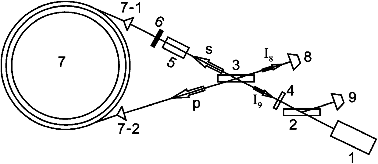
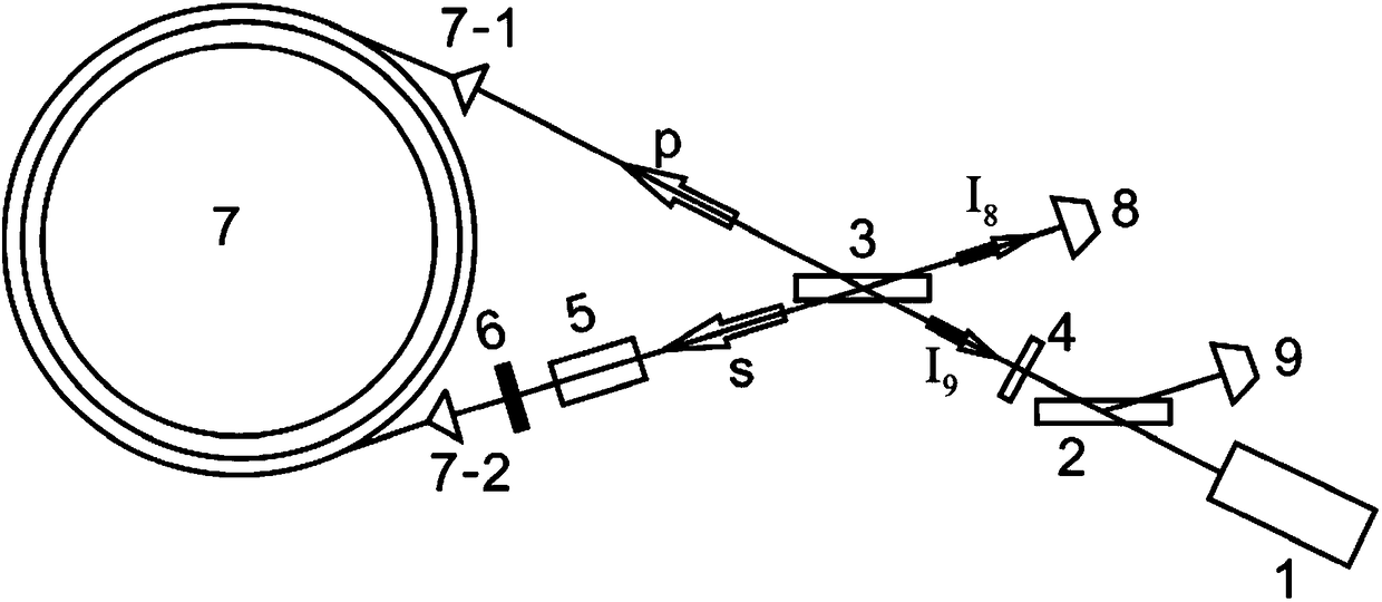
[0060] Laser source 1 adopts an external cavity tunable semiconductor laser, the model is Toptica DL100, the center wavelength is 780.24nm, the line width is 4MHz, the output power is 101mW, and the laser polarization state is linear polarization; the first beam splitter 2 and the second beam splitter 3 , diameter 10mm, splitting ratio 50:50; quarter-wave plate 4 is a true zero-order wave plate with a diameter of 10mm; atomic gas chamber 5 is 10mm 3 Quartz glass cavity, encapsulating rubidium atom vapor, but without adding buffer gas, pressure 10 -7 Torr, a nonlinear working medium that provides atomic spectroscopy; the attenuator 6 is a neutral filter with OD=2; the optical fiber loop 7 is wound by a 780nm optical fiber with a circumference of 500m, coated with a thermally conductive coating, and installed with a stable The mechanical structure of the loop area, the two ends of the optical fiber loop 7 are the first port 7-1 and the second port 7-2 with 780nm antireflection; ...


PUM


Abstract

The invention relates to a fiber gyroscope frequency stabilization apparatus and a frequency stabilization method thereof. Laser emitted by a laser light source goes through a first beam splitter and is divided into two laser paths, one of the two laser paths sequentially goes through a quarter wave plate and a second beam splitter, and is divided into two laser lights which are a pump laser s and a probe laser p, and the pump laser s goes through an atomic chamber, enters an optical fiber loop from a first port, and is emitted through a second port; the probe laser p enters the optical fiber loop from the second port, is emitted through the first port and goes through the atomic chamber, the laser paths of the pump laser s and the probe laser p coincide, the two emitted lasers go through the second beam splitter and are divided into a laser signal I8 and a laser signal I9, the laser signal I8 is received by a first photoelectric detector and is converted into a first electric signal, and the laser signal I9 sequentially goes through the quarter wave plate and the first beam splitter, is received by a second photoelectric detector and is converted into a second electric signal; and the sum of the two electric signals is the output signal of a fiber gyroscope, and a difference between the two electric signals is a frequency stabilization error signal.

Description

technical field [0001] The invention relates to the field of inertial measurement, in particular to an optical fiber gyroscope frequency stabilization device and a frequency stabilization method. Background technique [0002] The fiber optic gyroscope is a solid-state inertial device that uses the Sagnac effect of the fiber optic loop to measure the rotation of an object in the inertial space. It can measure the rotation angle or angular velocity by measuring the movement of the interference fringes. It is an important inertial navigation device. [0003] In the fiber optic gyroscope, the movement of the interference fringes is proportional to the rotational angular velocity, but it is also affected by the frequency of the laser light source. When the frequency of the laser light source jitters or drifts, the proportional relationship between the movement of the interference fringes and the rotational angular velocity also occurs. Changes, resulting in jitter or drift in the...

Claims


Application Information

Patent Timeline
Patent Type & Authority Patents(China)
IPC IPC(8): G01C19/72
CPCG01C19/721
Inventor 姜伯楠张国万李嘉华成永杰徐程魏小刚
Owner BEIJING INST OF AEROSPACE CONTROL DEVICES
Why Eureka
Try Eureka