
Method for removing residual non-uniform noise in thermal infrared image after non-uniform correction

A non-uniform correction and non-uniform noise technology, applied in image enhancement, image analysis, image data processing, etc., can solve problems such as affecting signal resolution, non-uniform noise in infrared images, and incomplete response characteristics of detection elements. To achieve the effect of reducing spatial noise

Active Publication Date: 2019-04-02
SHANGHAI INST OF TECHNICAL PHYSICS - CHINESE ACAD OF SCI
View PDF6 Cites 0 Cited by
  • Summary
  • Abstract
  • Description
  • Claims
  • Application Information

AI Technical Summary

Problems solved by technology

[0002] With the development of infrared imaging technology, people have higher and higher requirements for the sensitivity level of thermal infrared imaging systems, and the demand for obtaining higher-sensitivity infrared images is also more urgent. Needed, because even after non-uniformity correction, the infrared image still has residual non-uniform spatial noise, which will greatly affect the resolution of the signal in high-sensitivity occasions, and new measures must be taken to further improve the sensitivity of the infrared image Level
High-sensitivity infrared imaging systems generally use cooled infrared focal plane devices. Since the response characteristics of each detector element in the focal plane array are not completely consistent, different detection photosensitive elements will produce different output signals for the same infrared radiation, making the infrared image appear abnormal. uniform noise
The conventional non-uniformity correction algorithm cannot completely remove the noise, but the residual noise does not affect the image quality in general applications, so it can be seen that there is no method to further remove the non-uniform noise in the infrared image after non-uniform processing

Method used


Image

  • Method for removing residual non-uniform noise in thermal infrared image after non-uniform correction
  • Method for removing residual non-uniform noise in thermal infrared image after non-uniform correction
  • Method for removing residual non-uniform noise in thermal infrared image after non-uniform correction

Examples


Embodiment Construction

[0025] The present invention will be further described in detail below in conjunction with the embodiments and the accompanying drawings, but the embodiments of the present invention are not limited thereto.

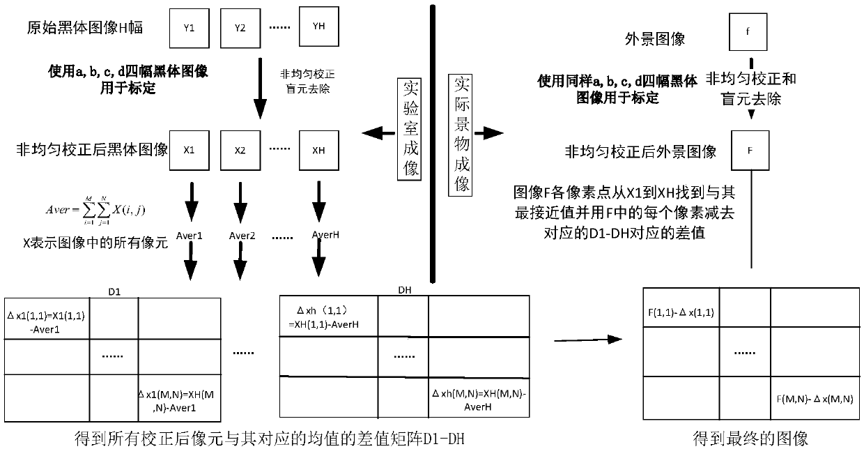
[0026] Such as figure 1 , taking the infrared imaging system with 320×256 focal plane as the hardware as an example, the improved method for removing residual non-uniform spatial noise in the infrared system includes the following steps:

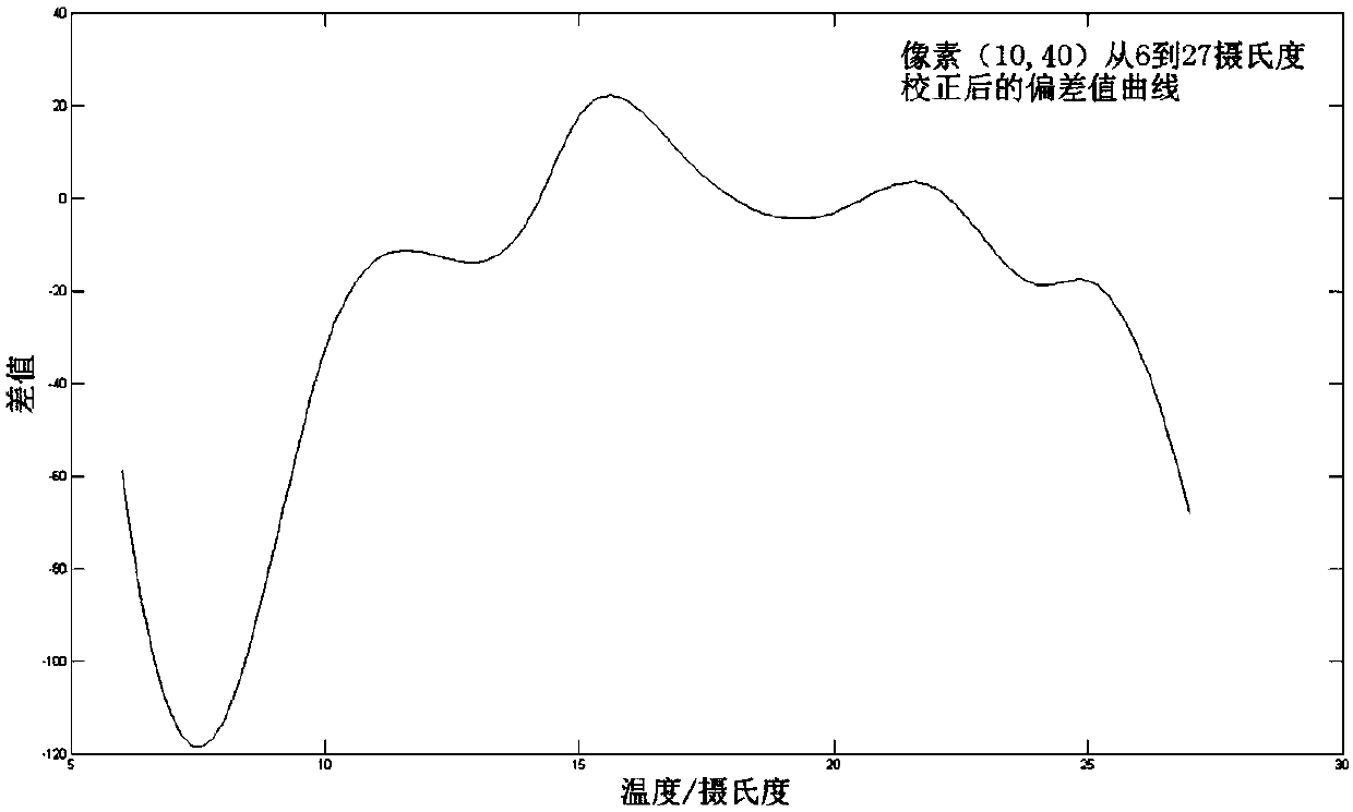
[0027] 1) Using an infrared imaging system, image a uniform black body at 6, 8, 10, 12, 14, 15, 17, 20, 22, 24, 25, and 27 degrees Celsius, and obtain 12 black body images Y 1 , Y 2 、…Y 12 , with varying temperature intervals.

[0028] 2) Select four blackbody images F at four temperatures of 10, 15, 20, and 25 degrees Celsius 1 , F 2 , F 3 , F 4 As a standard image for non-uniformity correction. Use these four images to perform non-uniform correction on the 12 blackbody images obtained in 1), and obtain 12 corrected blackbody ...


PUM


Abstract

The invention discloses a method for removing residual non-uniform noise in thermal infrared images after non-uniform correction. The implementation steps are as follows: 1) Use an infrared imaging system to image a black body at different temperatures to obtain an infrared image; 2) Perform non-uniform correction on the obtained black body image; 3) Obtain the pixel average value of the corrected black body image; 4) Each pixel value in the corrected blackbody image is subtracted from its average value and the result is stored; 5) Take the outdoor image and perform non-uniform correction; 6) Compare the corrected image pixel value with the average value of the image at different temperatures to find the closest value The corresponding subtraction array subtracts the pixel value from the value at the corresponding position in the array to obtain a new image. The invention makes up for the shortcomings of traditional infrared image noise removal methods and provides a more effective and accurate method for removing remaining non-uniform spatial noise. The invention can effectively remove the remaining non-uniform spatial noise in the infrared image without losing the original image information and obtain a high-quality restored image.

Description

Technical field: [0001] The invention belongs to the technical field of high-sensitivity infrared imaging and its application, is based on a cooling type infrared imaging hardware system, and relates to the removal of residual spatial noise after non-uniform correction of infrared images. Background technique: [0002] With the development of infrared imaging technology, people have higher and higher requirements for the sensitivity level of thermal infrared imaging systems, and the demand for obtaining higher-sensitivity infrared images is also more urgent. Needed, because even after non-uniformity correction, the infrared image still has residual non-uniform spatial noise, which will greatly affect the resolution of the signal in high-sensitivity occasions, and new measures must be taken to further improve the sensitivity of the infrared image Level. High-sensitivity infrared imaging systems generally use cooled infrared focal plane devices. Since the response characteris...

Claims


Application Information

Patent Timeline
Patent Type & Authority Patents(China)
IPC IPC(8): G06T5/00
CPCG06T2207/10048G06T5/70
Inventor 姬弘桢王建宇李春来孙羽金健陈小文
Owner SHANGHAI INST OF TECHNICAL PHYSICS - CHINESE ACAD OF SCI
Learn More