Flap-topped sine waveguide slow wave structure

A technology of sine waveguide and slow wave structure, which is applied in the field of flat-top sine waveguide slow wave structure, millimeter wave, and terahertz band vacuum electronic devices, and can solve the problems of long saturation interaction length, low interaction efficiency, and weak electric field strength, etc. problem, to achieve the effect of increased interaction capability, increased output power, and high coupling impedance value

Inactive Publication Date: 2016-08-17
UNIV OF ELECTRONICS SCI & TECH OF CHINA
View PDF6 Cites 13 Cited by
  • Summary
  • Abstract
  • Description
  • Claims
  • Application Information

AI Technical Summary

Problems solved by technology

However, the electric field strength of this structure in the direction of electromagnetic wave transmission is relatively weak, so its coupling impedance is small, r...

Method used


Image

  • Flap-topped sine waveguide slow wave structure
  • Flap-topped sine waveguide slow wave structure
  • Flap-topped sine waveguide slow wave structure

Examples


Embodiment Construction

[0017] Specific embodiments of the present invention will be described below in conjunction with the accompanying drawings, so that those skilled in the art can better understand the present invention. It should be noted that in the following description, when detailed descriptions of known functions and designs may dilute the main content of the present invention, these descriptions will be omitted here.

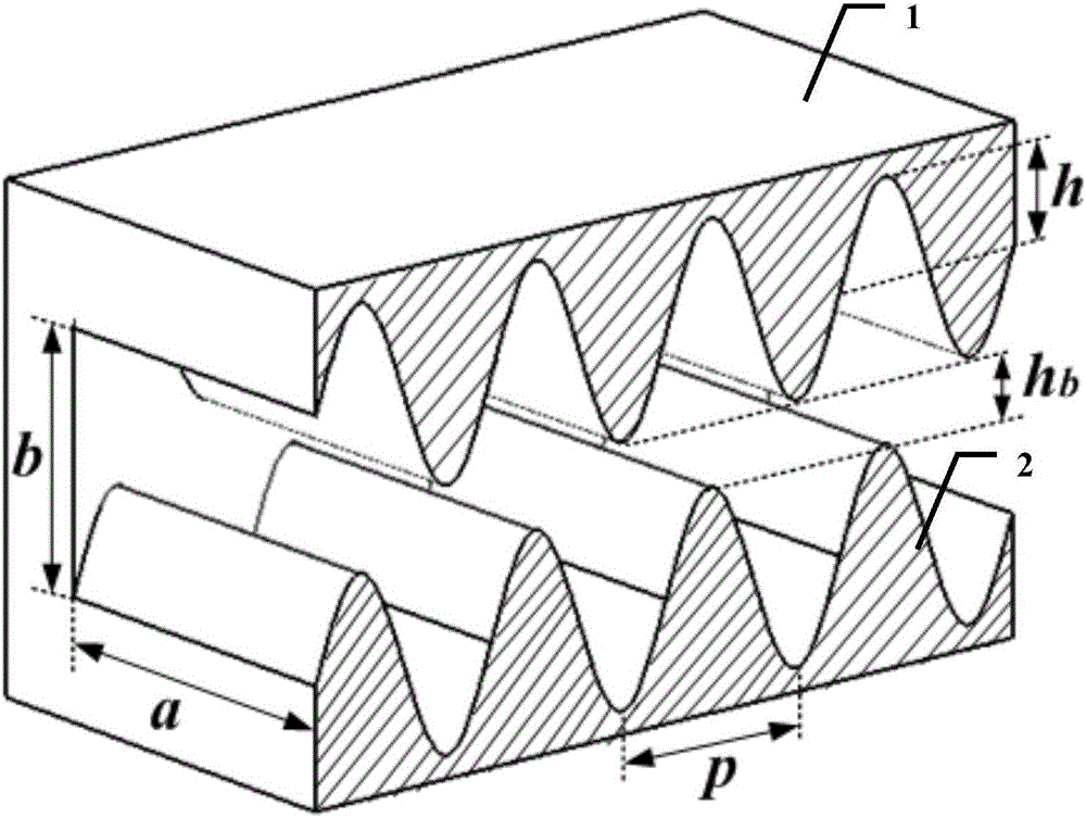
[0018] figure 1 It is a structural schematic diagram of a sinusoidal waveguide slow wave structure in the prior art.

[0019] In this embodiment, the existing sine waveguide slow wave structure such as figure 1 As shown, a is the length of the broad side of the waveguide, b is the length of the narrow side of the waveguide, h is the height of the periodic banding of the sinusoidal line, p is the period length of the sinusoidal line, and the width of the periodic banding of the sinusoidal line is a. In this embodiment, in the 220GHz frequency band, the structural dimension...


PUM


Abstract

The invention discloses a flat-topped sine waveguide slow wave structure. The size b of a narrow side is compressed appropriately on the basis of a sine waveguide slow wave structure, and the compression size is equal to the height of periodical strip fluctuation cut-tops of upper and low sine lines, so that the size parameter meets the condition that b is smaller than the sum of hb and 2h, wherein hb is the height of a sheet electron beam channel and h is the height of periodical strip fluctuations of the sine lines. Tests show that the flat-topped sine waveguide slow wave structure has a higher coupling impedance value, the dispersion characteristic is improved, increase of traditional coupled impedance is prevented, the defect that the dispersion characteristic is reduced is overcome, the interactive capacity between electron beams and electromagnetic waves is improved, and the output power, the gain and the interaction efficiency of traveling-wave tubes are improved.

Description

technical field [0001] The invention belongs to the technical field of vacuum electronics, and more specifically relates to a flat-top sine waveguide slow-wave structure, which is suitable for vacuum electronic devices in the millimeter wave and terahertz bands. Background technique [0002] Terahertz waves are electromagnetic waves with frequencies between microwave and infrared bands, which play an important role in high-speed space communication, ultra-high resolution weapon guidance, medical imaging, material terahertz spectral feature analysis, security inspection, material detection, etc. research value and broad application prospects. Vacuum electronic devices are a promising device that can realize high-power terahertz wave radiation sources. Traveling wave tube is a kind of millimeter wave and terahertz radiation source widely used in vacuum electronic devices. It has the characteristics of high power, high efficiency, high gain, wide frequency band and long life. ...

Claims


Application Information

Patent Timeline
IPC IPC(8): H01J23/24H01J23/28
CPCH01J23/24H01J23/28
Inventor 张鲁奇魏彦玉徐进丁冲王媛媛赵国庆岳玲娜
Owner UNIV OF ELECTRONICS SCI & TECH OF CHINA
Why Eureka
Try Eureka