A Low Disturbance Horn Antenna Bracket

A horn antenna, low-disturbance technology, applied to antenna supports/installation devices, antennas suitable for movable objects, etc., can solve the problem that the three-legged expansion angle cannot be guaranteed to be the same, the shape and weight of the antenna are different, and the replacement Antenna inconvenience and other problems, to achieve the effect of improving test efficiency, avoiding human disturbance, and improving test accuracy

Active Publication Date: 2019-04-26
CHINA SHIP DEV & DESIGN CENT
View PDF6 Cites 0 Cited by
  • Summary
  • Abstract
  • Description
  • Claims
  • Application Information

AI Technical Summary

Problems solved by technology

[0004] At present, multiple antennas are used in the field strength test. The shapes and weights of the antennas in different frequency bands are different, and the ways in which the antennas are installed on the brackets are also different. As a result, the current replacement of the antenna requires the cooperation of multiple people, and sometimes even requires the use of Special tools, time-consuming and labor-intensive
[0005] In addition, when the tripod is placed, the expansion angles of the three legs cannot be guaranteed to be the same, and the support points are not easy to balance, either high or low, and the metal materials used at the movable joints and bottom fulcrums affect the test accuracy, and the connection with the antenna is mostly 3mm to 4mm Screws, insufficient support strength, easy to break, and it is inconvenient to replace the antenna

Method used


Image

  • A Low Disturbance Horn Antenna Bracket
  • A Low Disturbance Horn Antenna Bracket

Examples


Embodiment Construction

[0025] The present invention will be described in detail below in conjunction with the accompanying drawings and embodiments.

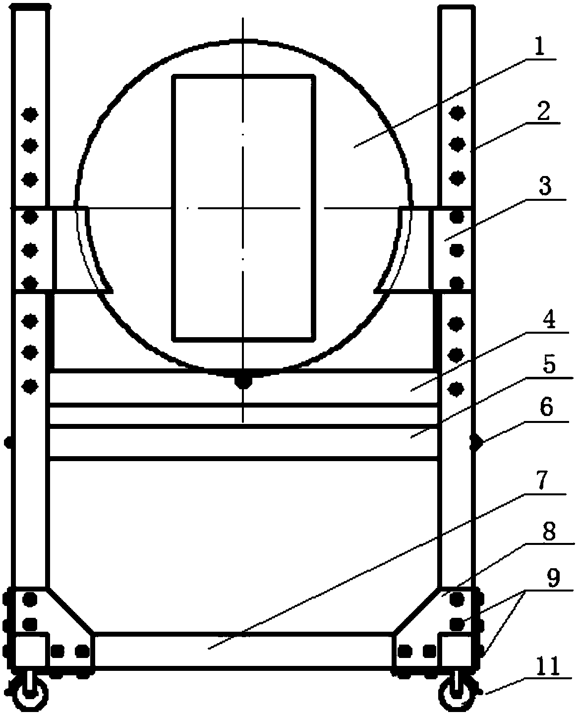
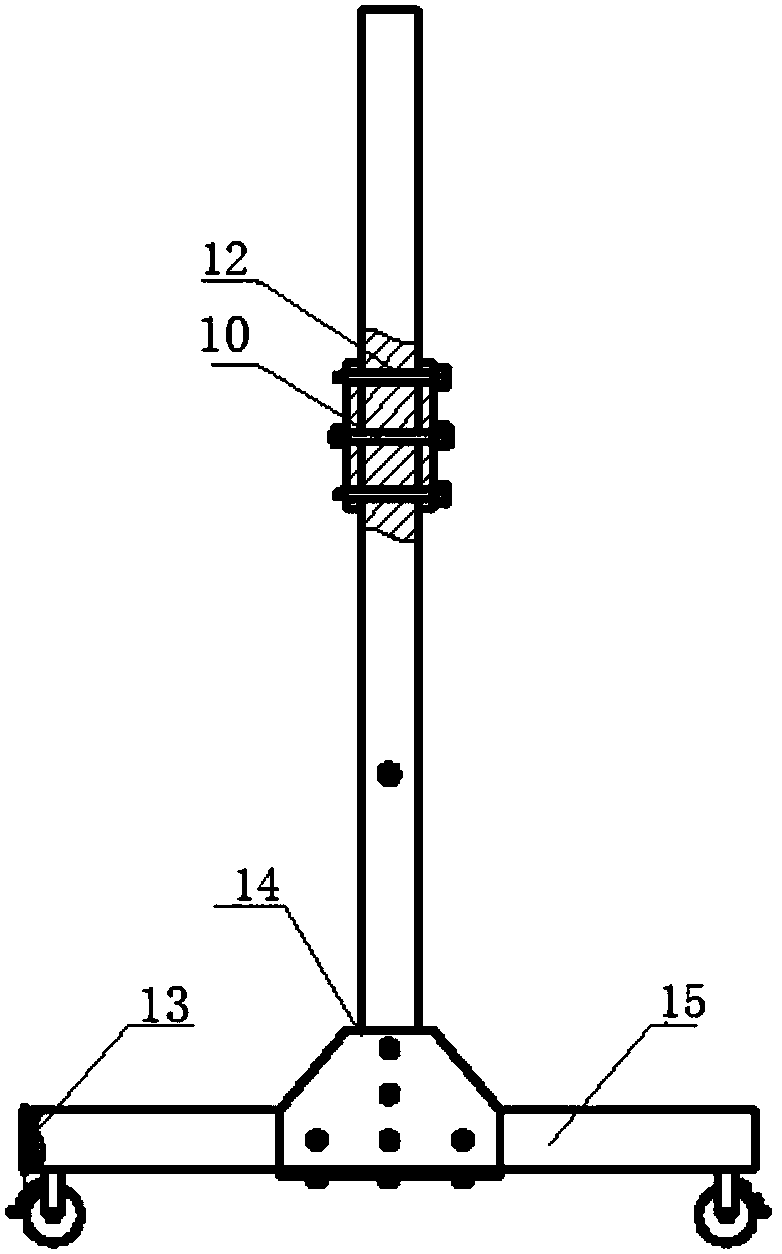
[0026] refer to Figure 1 ~ Figure 2 As shown, the low-disturbance horn antenna bracket in an embodiment provided by the present invention includes a fixed bracket, a movable bracket and a disc clamp 1, the movable bracket is arranged above the fixed bracket, and a vertical track is provided on the fixed bracket, and the movable bracket can be Move and adjust up and down along the vertical track, there is a chute in the movable bracket, the disc clamp 1 is placed in the chute, the disc clamp 1 can rotate in the chute, and the middle part of the disc clamp 1 is provided with a mounting hole for Install the antenna; by turning the disk fixture 1 in the chute, the polarization of the antenna is converted, and it is not necessary to disassemble the antenna again because of the transformation of the antenna polarization. It is especially suitable for insta...


PUM


Abstract

The invention discloses a low-disturbance horn antenna bracket, which is characterized in that it comprises a fixed bracket, a movable bracket and a disc clamp, the movable bracket is arranged above the fixed bracket, and a vertical track is arranged on the fixed bracket, and the movable bracket can move along the vertical The track moves up and down to adjust, the movable bracket is provided with a chute, the disc clamp is placed in the chute, the disc clamp can rotate in the chute, and the middle part of the disc clamp is provided with a mounting hole for installing the antenna. Antenna polarization conversion, installation and disassembly are convenient, and only one person is required to operate, which greatly saves manpower and test time, improves test efficiency, and improves measurement stability.

Description

technical field [0001] The invention relates to the technical field of electromagnetic compatibility testing, in particular to a low-disturbance horn antenna bracket. Background technique [0002] At present, high-power and high-frequency equipment on surface ships is gradually increasing, and the electromagnetic environment of surface ships is becoming more and more complex. In order to understand and control the electromagnetic environment of ships, the electromagnetic compatibility performance indicators of key equipment in ships should be controlled first, and Compatibility testing is the most effective means to discover equipment electromagnetic compatibility problems. The current test tasks are increasing rapidly, and the test efficiency needs to be greatly improved. Develop corresponding test brackets, connectors and other accessories, which can quickly move and replace antennas, facilitate the erection of various antennas in various test environments, and can also s...

Claims


Application Information

Patent Timeline
Patent Type & Authority Patents(China)
IPC IPC(8): H01Q1/12H01Q1/34
CPCH01Q1/12H01Q1/34
Inventor 黄琼张嘉陆健任平郭子亮
Owner CHINA SHIP DEV & DESIGN CENT
Why Eureka
Try Eureka