Connector device with cantilever structure

A connector and cantilever technology, applied in the field of connector devices with cantilever structure, can solve problems such as loss and secondary lock damage, and achieve the effects of avoiding damage and loss, strong anti-loss function and good safety.

Pending Publication Date: 2016-08-17
DELPHI ELECTRICAL CENTS SHANGHAI CO LTD
View PDF3 Cites 1 Cited by
  • Summary
  • Abstract
  • Description
  • Claims
  • Application Information

AI Technical Summary

Problems solved by technology

[0003] In the existing automotive connector design process, the CPA (connector secondary lock, hereinafter referred to as the secondary lock) is usually designed as a separate piece. This old design is easy to cause damage to the secondary lock and loss during use.

Method used


Image

  • Connector device with cantilever structure

Examples


Embodiment

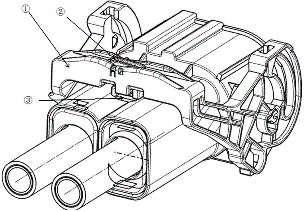
[0017] Such as figure 1 As shown, a connector device with a cantilever structure includes a connector body 3, a cantilever 1 and a secondary lock 2. The secondary lock 2 is embedded in the cantilever 1, and the cantilever 1 and the connector body 3 After the locking connection, the secondary lock 2 is locked and connected with the connector body 3.

[0018] The longitudinal section of the cantilever 1 is an inverted U-shaped structure, and the whole is an earmuff-shaped structure. The cantilever 1 is provided with a fixing hole for installing a secondary lock, and the secondary lock is inserted into the fixing hole and locked and connected with the connector. The fixing hole is set at the center of the upper surface of the cantilever.

[0019] The mating and disengagement of the connector body can be controlled by the rotation of the cantilever, and a lock function is provided. The built-in secondary lock provides the secondary lock function again when the cantilever lock i...


PUM


Abstract

The invention relates to a connector device with a cantilever structure. The connector device comprises a connector body, a cantilever and a secondary lock; the secondary lock is embedded on the cantilever; and after the cantilever is in locking connection with the connector body, and the secondary lock is in locking connection with the connector body. Compared with the prior art, the connector device of the invention has the advantages of strong anti-loss function, high safety and the like.

Description

technical field [0001] The invention relates to a connector, in particular to a connector device with a cantilever structure. Background technique [0002] Automotive connectors are a component that electronic engineers and technicians often come into contact with. Its function is very simple: to build a bridge of communication between the blocked or isolated circuits in the circuit, so that the current can flow and the circuit can realize the predetermined function. The form and structure of automotive connectors are ever-changing. It is mainly composed of four basic structural components, namely: contacts, shells (depending on the variety), insulators, and accessories. [0003] In the existing automotive connector design process, the CPA (connector secondary lock, hereinafter referred to as the secondary lock) is usually designed as a separate piece. This old design is easy to cause damage to the secondary lock and loss during use. Contents of the invention [0004] Th...

Claims


Application Information

Patent Timeline
Patent Type & Authority Applications(China)
IPC IPC(8): H01R13/639H01R13/502
Inventor 庄友良胡林涛
Owner DELPHI ELECTRICAL CENTS SHANGHAI CO LTD
Why Eureka
Try Eureka