Driving method and device for IGBT provided with push-and-pull isolating power source

A technology for isolating power supplies and driving devices, which is applied in the direction of output power conversion devices, electrical components, and adjusting electrical variables, etc. It can solve problems such as difficult control of distributed capacitance, high cost of driving devices, and complicated secondary windings of isolated power transformers.

Inactive Publication Date: 2016-08-17
LUOYANG CITIC HIC AUTOMATION ENG
View PDF3 Cites 6 Cited by
  • Summary
  • Abstract
  • Description
  • Claims
  • Application Information

AI Technical Summary

Problems solved by technology

It can be seen from the above schemes that some of these driving devices have low utilization rate of isolated power transformers, some circuits use more components, and some increase the complexity of transformer windings, resulting in high cost of driving devices. Big size
At the same time, the secondary winding of the isolated power transformer is complicated, which not only increases the difficulty of transformer design, but also is unfavorable to the size and cost of the transformer; more importantly, the complexity of the secondary winding of the isolated power transformer makes the distributed capacitance of the primary and secondary sides of the isolated power transformer difficult. control, resulting in a decrease in the ability of the driver's primary and secondary sides to suppress common-mode interference, a decrease in the anti-interference ability of the drive device, and unstable factors in the system

Method used


Image

  • Driving method and device for IGBT provided with push-and-pull isolating power source
  • Driving method and device for IGBT provided with push-and-pull isolating power source
  • Driving method and device for IGBT provided with push-and-pull isolating power source

Examples


Embodiment Construction

[0025] The present invention will be described in further detail below in conjunction with the accompanying drawings.

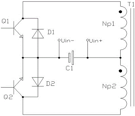
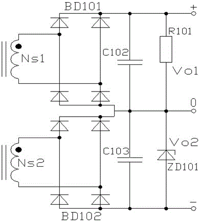
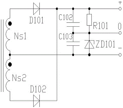
[0026] combined with Figure 5 , 6 As shown, an IGBT drive device configured with a push-pull isolated power supply includes: a primary side drive circuit, a secondary side drive circuit, a push-pull DCDC isolated power supply circuit, and the PWM shaping circuit of the primary side drive circuit communicates with the secondary side through the photoelectric isolation circuit. The input terminal of the side drive circuit is connected, the feedback terminal of the secondary side drive circuit is connected with the fault signal latch circuit of the primary side drive circuit through the fault feedback circuit, the output terminal of the secondary side drive circuit is connected with the IGBT module; the PWM shaping circuit input of the primary side drive circuit The terminal, the output terminal of the fault signal latch circuit, and the push-pull DCDC isolate...


PUM


Abstract

The invention relates to the technical field of IGBT driving and provides a driving method and device for an IGBT provided with a push-and-pull isolating power source. The driving device adopted in the method comprises a primary side driving circuit, a secondary side driving circuit and a push-and-pull DCDC isolating power source circuit; a PWM shaping circuit of the primary side driving circuit is connected with the input end of the secondary side driving circuit through a photoelectric isolating circuit; the feedback end of the secondary side driving circuit is connected with a fault signal latch circuit of the primary side driving circuit through a fault feedback circuit; the output end of the secondary side driving circuit is connected with an IGBT module; the input end of the PWM shaping circuit, the output end of the fault signal latch circuit and the push-and-pull isolating power source circuit are connected with a driver interface. By controlling primary and secondary distributed capacitance of a transformer, the common-mode rejection capacity of the driving device is improved, and the anti-jamming capability of the driving device is enhanced; the isolating power source circuit is simplified, and the cost of the driving device is lowered; the size of the driving device is reduced, and the driving device is high in practicability and reliability.

Description

technical field [0001] The invention relates to the technical field of IGBT driving, in particular to an IGBT driving method and device configured with a push-pull isolated power supply, which is suitable for compact and low-cost IGBT driving occasions. Background technique [0002] In IGBT applications, the IGBT drive device not only plays an important role in the reliability of the entire system, but also has an important impact on the miniaturization and low cost of the entire system. Because the drive circuit using the dedicated IC with photoelectric isolation technology as the core device has the characteristics of flexible design, small size, high stability and reliability, it is widely used in IGBT applications that require high system volume and cost. The drive circuit using a special IC for photoelectric isolation technology generally needs to be configured with an isolated power supply outputting a positive and negative common ground voltage to form a complete set ...

Claims


Application Information

Patent Timeline
Patent Type & Authority Applications(China)
IPC IPC(8): H02M3/337H02M3/338
CPCH02M3/337H02M3/3382
Inventor 王浩然周秋燕黄新明邱玉林何腾飞张书明
Owner LUOYANG CITIC HIC AUTOMATION ENG
Why Eureka
Try Eureka