
Prosthetic knee joint

A technology of knee joints and joints, which is applied in the field of prosthetic knee joints, can solve problems such as geometric locking of the joint system and complex structure of prosthetic knee joints, and achieve maintenance-free and low-noise effects

Active Publication Date: 2016-08-17
OTTO BOCK HEALTHCARE IP GMBH & CO KG
View PDF7 Cites 7 Cited by
  • Summary
  • Abstract
  • Description
  • Claims
  • Application Information

AI Technical Summary

Problems solved by technology

[0003] A problem with prosthetic knee joints with variable-length joint parts is the relatively complex structure and the possibility of geometrical locking of the joint system during descent during flexor contraction during the stance phase

Method used


Image

  • Prosthetic knee joint
  • Prosthetic knee joint

Examples


Embodiment Construction

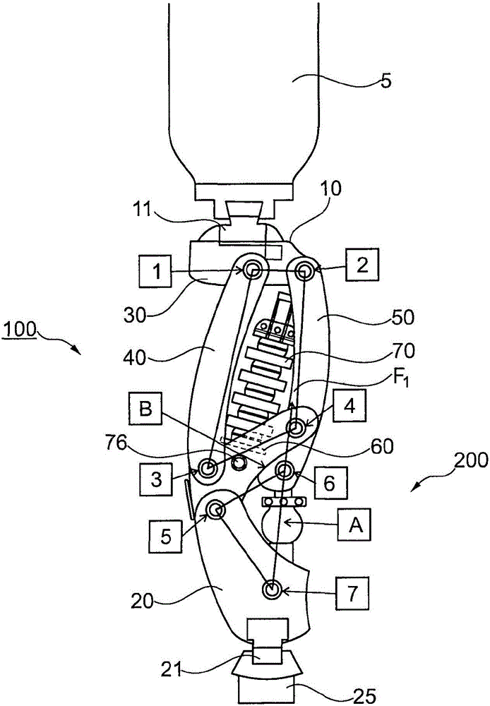
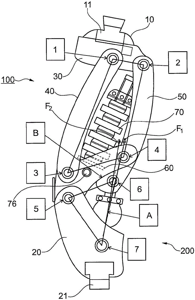
[0021] figure 1 The embodiment of the prosthetic knee joint shown in has an upper part 10 on which a fastening device 11 configured as a joint hanger for the telecentric prosthetic part 5 is arranged, for example for fastening the prosthetic knee joint to On the thigh tube or on the thigh barrel. The fastening device 11 can be screwed into the upper part 10 or can be integrally formed thereon. The first joint part 30 of the four-part joint system 100 can be arranged or formed on the upper part 10 . The proximal, substantially horizontally oriented joint part 30 has an anterior pivot axis 1 and a posterior pivot axis 2 . A front joint member 40 is pivotally supported on the front pivot shaft 1 , and a rear joint member 50 is pivotally supported on the rear pivot shaft 2 . Thus, the proximal end of the front joint part 40 is pivotably connected via the pivot axis 1 and the proximal end of the rear joint part 50 via the pivot axis 2 to the upper part 10 or to the proximal join...


PUM


Abstract

The invention relates to a prosthetic knee joint comprising an upper part (10), a lower part (20) which is arranged pivotably to the upper part (10), a fastening device (11) arranged on the upper part (10) for a proximal prosthetic element, a fastening device (21) arranged on the lower part (20) for a distal prosthetic element, a four-limbed joint system (100) with four linkages (30, 40, 50, 60) articulatedly fastened to each other, which are each pivotable to each other around a pivot axis (1, 2, 3, 4), wherein the upper part (10) is arranged on the joint system (100), wherein the joint system (100) is mounted pivotably on the lower part (20) from a starting position counter to a spring force during a stance phase flexion, and the action line (F) of the spring force is aligned such that a moment acting against an inflexion of the joint system (100) is present.

Description

technical field [0001] The invention relates to a prosthetic knee joint with an upper part and a lower part pivotably arranged on the upper part, with a fastening device arranged on the upper part for a proximal prosthetic element, with a The fastening device for the telecentric prosthetic element on the lower part has a four-part joint system with four joint parts fixed to one another in an articulated manner, which are each pivotable relative to each other about a pivot axis Rotation, wherein the upper part is arranged on the joint system. Background technique [0002] EP 0 713 689 A1 shows a prosthetic knee joint with an upper part and a lower part which is fastened in an articulated manner to the upper part. The upper part and the lower part are coupled via a multi-part kinematic joint chain having at least four joint parts, in which the parts connected to each other are changed to have a common axis of rotation. The axes of rotation extend substantially parallel to ea...

Claims


Application Information

Patent Timeline
Patent Type & Authority Applications(China)
IPC IPC(8): A61F2/64A61F2/50
CPCA61F2002/5009A61F2002/5087A61F2/644A61F2/64A61F2/642A61F2002/5003A61F2002/5007
Inventor H·博伊特
Owner OTTO BOCK HEALTHCARE IP GMBH & CO KG
Learn More