
Multifunctional cutting machine

A slitting machine and multi-functional technology, which is applied in metal processing and other fields, can solve the problems of non-interchangeability and single function, and achieve the effect of reducing costs

Pending Publication Date: 2016-08-24
SHENZHEN NEW KATOP AUTOMATION TECH
View PDF6 Cites 10 Cited by
  • Summary
  • Abstract
  • Description
  • Claims
  • Application Information

AI Technical Summary

Problems solved by technology

[0003] In order to overcome the shortcomings of the existing slitting knife holders that have single functions and cannot be interchanged, the purpose of the present invention is to provide a multifunctional slitting machine that can be replaced between mechanical round knives and automatic row knives

Method used


Image

  • Multifunctional cutting machine
  • Multifunctional cutting machine
  • Multifunctional cutting machine

Examples


Embodiment Construction

[0019] The present invention will be described in further detail below in conjunction with the embodiments and with reference to the accompanying drawings.

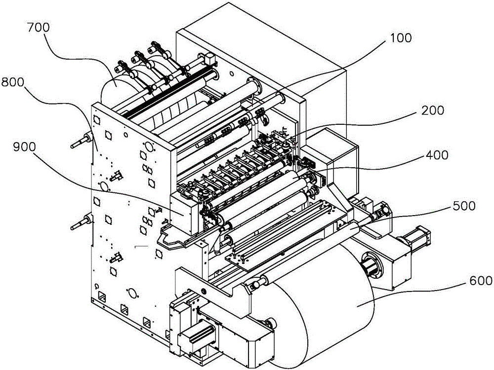
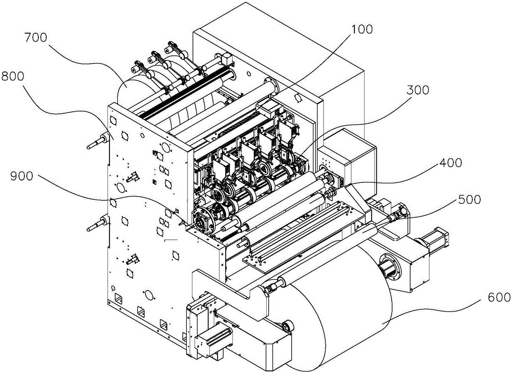
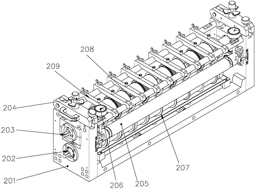
[0020] A multifunctional cutting machine, refer to Figure 1 to Figure 2 , including a frame 800, the front end of the frame 800 is provided with an unwinding module 600, the rear end of the frame 800 is provided with a rewinding module 700, and the middle part of the frame 800 is also provided with a knife holder installation port 900, the Knife rest mounting port 900 is detachably installed with mechanical circular knife knife rest 200 (refer to figure 1 ) or automatic tool holder 300 (refer to figure 2 ), the material on the unwinding module 600 is cut into a small material by the round knife on the mechanical round knife knife rest 200 or the row knife on the automatic knife row knife rest 300, and then by a plurality of winding rollers on the winding module 700 Roll up.

[0021] This multi-functional slitting mac...


PUM


Abstract

The invention discloses a multifunctional cutting machine. The machine comprises a rack, wherein an unwinding module is arranged at the front end of the rack; a winding module is arranged at the back end of the rack; a knife rest mounting port is further formed in the middle of the rack; a mechanical circular knife rest or an automatic row knife rest is detachably mounted at the knife rest mounting port; materials on the unwinding module are cut by circular knives on the mechanical circular knife rest or row knives on the automatic row knife rest into small materials, and then the small materials are wound by multiple winding rollers on the winding module. The machine has the advantage that the mechanical circular knives and the automatic row knives can be switched.

Description

technical field [0001] The invention relates to a slitting machine, in particular to a multifunctional slitting machine which can be replaced between a mechanical circular knife and an automatic row knife. Background technique [0002] The slitter is used for slitting the width of film or pole piece materials. Traditional slitting machines generally have fixed blades or round blades. The traditional slitting machine has a single function, and the various configurations cannot be interchanged. Traditional mechanical blade slitting machines need to replace the spacer between the blades when processing products of different specifications during use; the upper and lower knives use springs to provide engagement force, which is not easy to quantify and has low controllability; it is necessary to detect product burrs and edge trimming effects In order to judge whether the blade is passivated, and then determine whether to change the blade, the timeliness of maintenance is poor. ...

Claims


Application Information

Patent Timeline
Patent Type & Authority Applications(China)
IPC IPC(8): B26D11/00B26D7/26
CPCB26D7/2614B26D11/00B26D2011/005
Inventor 齐晓东樊振华樊新建
Owner SHENZHEN NEW KATOP AUTOMATION TECH
Learn More