

Mold removing machine
A mold-moving and mold-moving technology, applied in the field of mold-moving machines, can solve problems such as high labor costs, and achieve the effects of saving time and cost, alleviating high labor costs, and reducing manpower participation
- Summary
- Abstract
- Description
- Claims
- Application Information
AI Technical Summary
Problems solved by technology
Method used
Image

Examples
Embodiment 1
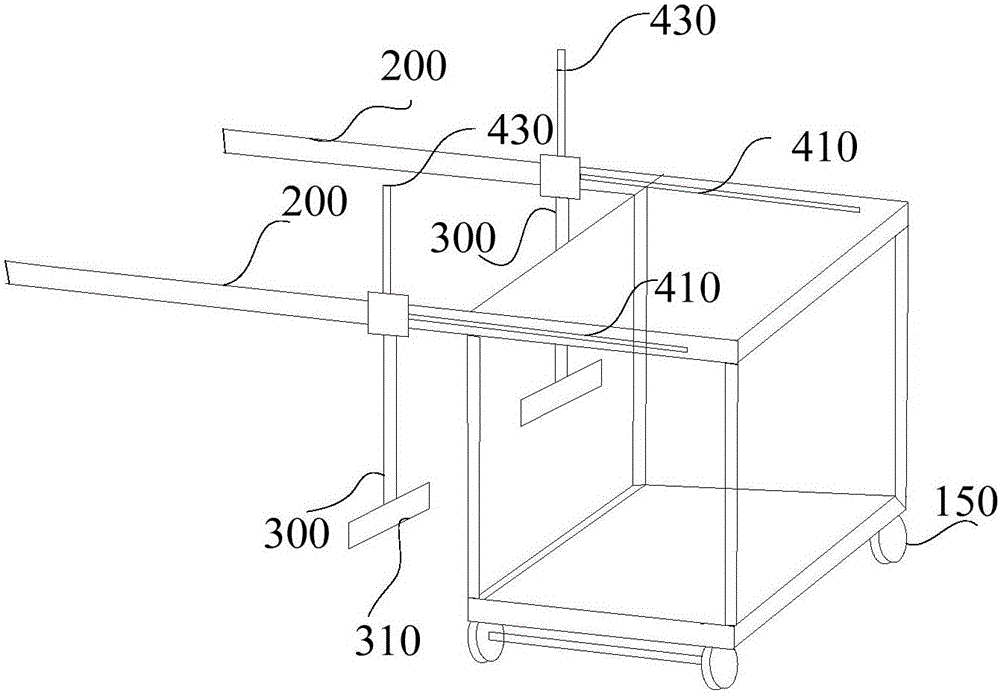
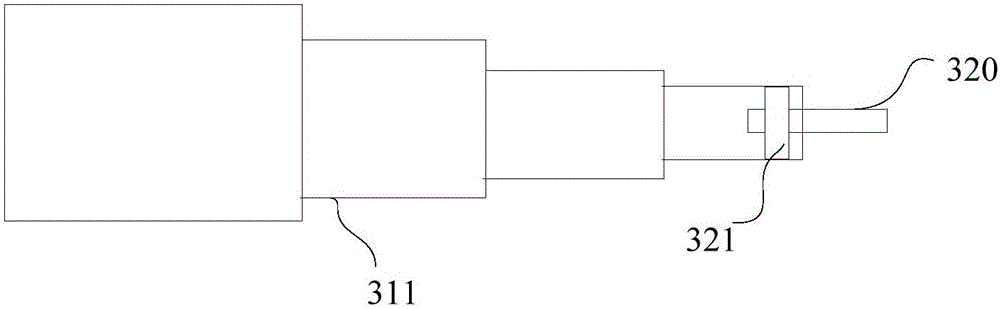
[0048] This embodiment provides a mold transfer machine, such as figure 1 As shown, the mold transfer machine body 100 is provided with a beam 200 on the mold transfer machine body 100; the cross beam 200 is provided with a first telescopic rod 300 that can move along the length direction of the beam 200; one end of the first telescopic rod 300 is arranged There is a grabbing device for grabbing the mould; the mold transfer machine also includes a hydraulic driving device 400 to provide power for the movement of the first telescopic rod 300 on the beam 200 .
[0049] The aforementioned grabbing device may be a device located at one end of the first telescopic rod for grabbing the mould. The grabbing device can be flexibly selected according to the structure of the specific mold. For example, for guardrail molds, the grabbing device can be a pin structure; for relatively small molds, the grabbing device can also be a gripper-like structure or The structure of the noose, etc., ...
Embodiment 2
[0074] Usually, molds are usually installed on both sides of highways, overpasses, etc., and the bolts on the mold are usually removed by workers. If workers stand on the road during work, it will be inconvenient to disassemble the bolts on the side of the mold away from the road. However, it is more dangerous to stand on the side of the mold away from the road to operate. This embodiment aims to solve this technical problem.
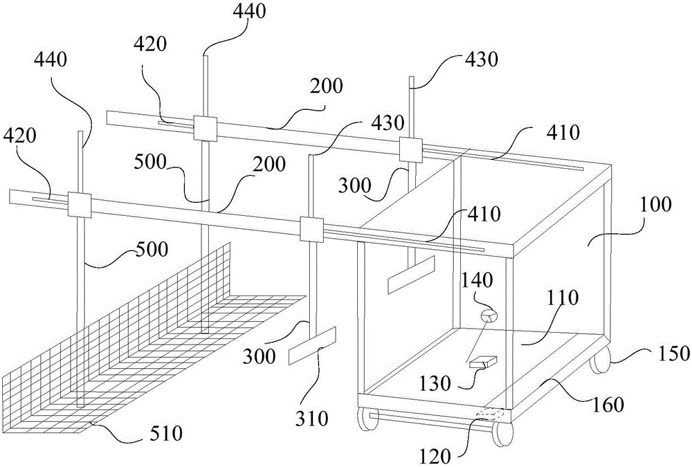
[0075] A kind of mold that present embodiment provides, such as figure 2 As shown, with the structure in the above-mentioned embodiment, on the side of the crossbeam 200 away from the mold transfer machine body 100, a second telescopic rod 500 that can move along the length direction of the crossbeam 200 is intersected; the hydraulic drive device 400 is the second telescopic rod The movement of the 500 on the crossbeam 200 provides power; one end of the second telescopic rod 500 is provided with a human stand 510 for the operator to stand on.
[0076]...
Embodiment 3
[0080] This embodiment provides a mold transfer machine, such as figure 2 , Figure 4 As shown, including the mechanism in the above embodiment, there are two beams 200, which are arranged in parallel on both sides of the mold transfer machine body 100; the mold transfer machine body 100 is provided with a mold transfer machine chassis 110, on which A hydraulic motor 120, a hydraulic pump 130, and a steering wheel 140 are provided, and wheels 150 are provided at the bottom of the mold transfer machine body 100; the hydraulic pump 130 provides hydraulic energy for the hydraulic motor 120; the hydraulic motor 120 provides power for the movement of the mold transfer machine body 100. The mold transfer machine body includes: a counterweight slot 160 arranged in the mold transfer machine body 100 , and the counterweight slot 160 is used for placing counterweight objects to balance the weight on the beam 200 .
[0081] Among them, such as figure 2 , Figure 5 As shown, the hydr...
PUM
 Abstract
Description
Claims
Application Information