
A damping buffer structure for furniture

A buffer structure and furniture technology, which is applied to furniture parts, home appliances, building structures, etc., can solve the problems of complex structure of automatic opening devices, inability to meet user needs, and lack of anti-fall retention, etc. Simple and reasonable structure, improve the effect of internal use position

Active Publication Date: 2017-08-25
伍志勇
View PDF1 Cites 0 Cited by
  • Summary
  • Abstract
  • Description
  • Claims
  • Application Information

AI Technical Summary

Problems solved by technology

However, the automatic opening device of the drawer slide rail of this structure has a complex structure, and the operation is not flexible enough in the actual use process, and a locked state will occur during its operation, and this structure can only be used for the drawer slide rail, not for sliding doors. , the scope of use is small, and it does not have the function of anti-slip retention, which cannot meet the needs of users

Method used


Image

  • A damping buffer structure for furniture
  • A damping buffer structure for furniture
  • A damping buffer structure for furniture

Examples


no. 1 example

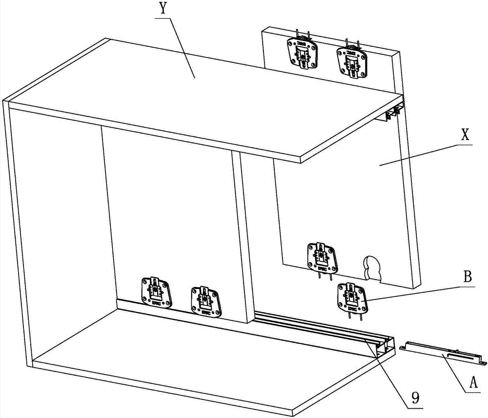
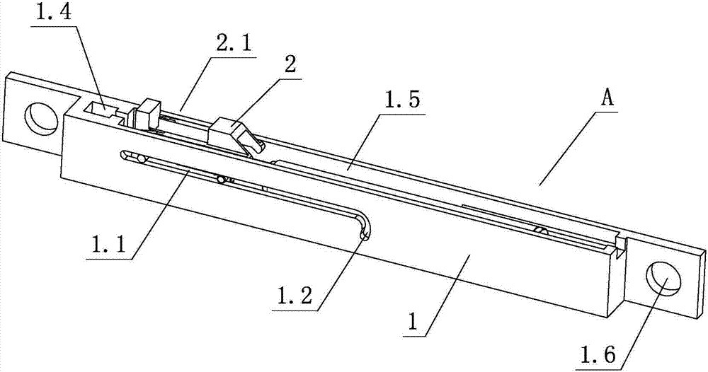
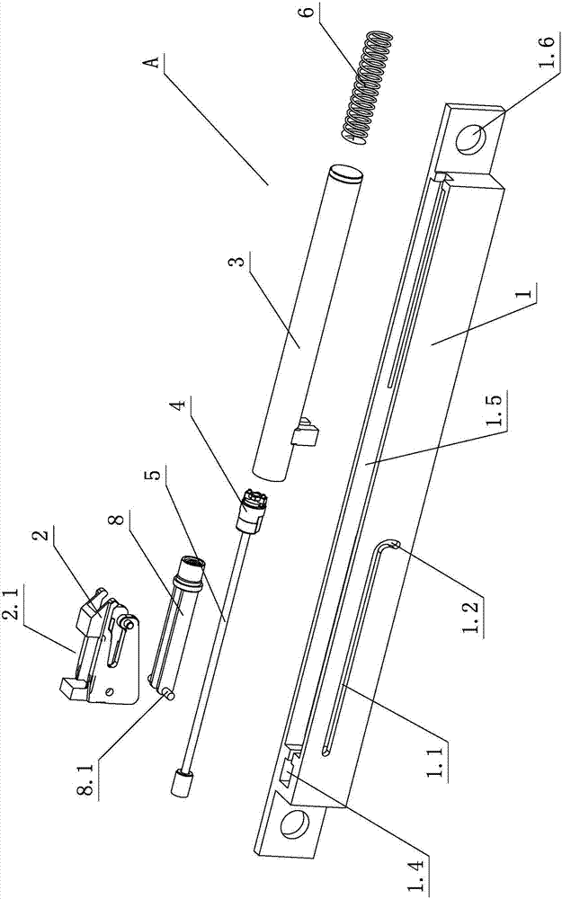
[0027] see Figure 1-Figure 9 , the furniture damping buffer structure includes a damping device A, the damping device A includes a fixed bracket 1, a swing element 2, a damper and an elastic element, and the damper is at least composed of a cylinder 3, a piston 4 and a piston rod 5, and the piston 4 is arranged on In the cylinder body 3, one end of the piston rod 5 extends into the cylinder body 3 and is connected with the piston 4, and the other end extends out of the cylinder body 3 and is fixedly arranged on the fixed bracket 1, and the cylinder body 3 is slidably arranged on the fixed bracket 1 , the fixed bracket 1 is provided with a linear sliding area 1.1 and a curved standby area 1.2, the swing element 2 is slidably arranged on the linear sliding area 1.1 and the curved standby area 1.2, and swings or rotates between the piston rod 5 and the cylinder body 3, elastic One end of the element elastically acts on the swing element 2 or the damper, and the other end elastic...

no. 2 example

[0040] see Figure 10 , this furniture damping buffer structure is different from the first embodiment in that: the moving part is the furniture sliding rail C, and the fixed part is the furniture fixing sliding rail D; the toggle device B is arranged on the furniture moving sliding rail On C, the damping device A is set on the fixed slide rail D of the furniture, or the damping device A is set on the movable slide rail C of the furniture, and the toggle device B is set on the fixed slide rail D of the furniture.

[0041] Other unmentioned parts are the same as the first embodiment.


PUM


Abstract

A furniture damping buffer structure comprises a damping device, wherein the damping device comprises a fixed support, a swinging element, a damper and an elastic element, wherein the damper at least comprises a cylinder body, a piston and a piston rod; the piston rod is arranged in the cylinder body; one end of the piston rod extends into the cylinder body and is connected with the piston; the other end of the piston rod extends out of the cylinder body and is fixedly arranged on the fixed support; the cylinder body is slidably arranged on the fixed support; a linear sliding region and a curved standby region are arranged on the fixed support; the swinging element is slidably arranged on the linear sliding region and the curved standby region and swings or rotates between the piston rod and the cylinder body; one end of the elastic element elastically acts on the swinging element or the damper; the other end of the elastic element elastically acts on the fixed support; and when the swinging element slides to the linear sliding region from the curved standby region, the elastic element drives the cylinder body to slide towards the direction of the piston rod, so that the length of the piston rod extending out of the cylinder body is reduced gradually, and the damper compresses and generates a buffer force. By improvement of the structure, the furniture damping buffer structure is high in practicality.

Description

technical field [0001] The invention relates to a furniture damping buffer structure. Background technique [0002] Chinese patent CN2803114Y disclosed on August 9, 2006 an automatic opening device for drawer slide rails. The sliding hook is provided by the chute of the fixed seat connected to the slide rail of the cabinet body, and is locked on the drawer. The linkage of the linkage rod of the slide rail and the elastic return force of the elastic element cooperate with the positioning axis of the rocker pivoted by the fixed seat and the introduction channel, catch channel and export support groove on the back of the slide hook. It is said that the guide of the channel and the outlet channel can achieve the automatic opening function of the drawer after being pressed; in addition, when the drawer is to be opened, the drawer must be pressed so that it slides inward for more than a certain distance, so that the automatic opening can be achieved. Function, so that the drawer ...

Claims


Application Information

Patent Timeline
Patent Type & Authority Patents(China)
IPC IPC(8): E05F3/10A47B88/473
CPCA47B2210/0018E05F3/108E05Y2600/626E05Y2900/20
Inventor 伍志勇
Owner 伍志勇
Learn More