
Anti-rotating bolt

An anti-rotation and bolt technology, applied in the direction of bolts, screws, nuts, etc., can solve problems such as easy rotation and affect installation efficiency, and achieve the effect of improving installation efficiency and connection efficiency

Inactive Publication Date: 2016-08-24
ZUNYI QINLE HARDWARE BUILDING MATERIAL PROCESSING FACTORY
View PDF5 Cites 3 Cited by
  • Summary
  • Abstract
  • Description
  • Claims
  • Application Information

AI Technical Summary

Problems solved by technology

[0003] The purpose of the present invention is to provide an anti-rotation bolt to solve the problem that the traditional bolts are easy to rotate and affect the installation efficiency when they need to be installed in the counterbore

Method used


Image

  • Anti-rotating bolt

Examples


Embodiment Construction

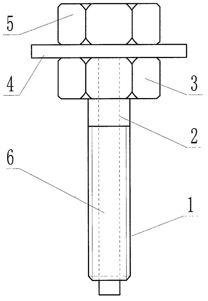
[0012] The technical scheme of the present invention will be further described below in conjunction with the accompanying drawings, but the required protection scope is not limited to the description;

[0013] Such as figure 1 As shown, the anti-rotation bolt provided by the present invention includes a screw 2 with a nut 3 at the top and a threaded segment 1 at the end. A limit rod 6 with matching dimensions, the top end of the limit rod 6 is fixedly connected with a handle 5 and a baffle plate 4 .

[0014] In order to improve the scope of application of the present invention and ensure the strength of the screw 2, the limiting rod 6 and the through hole are triangular, rectangular or hexagonal.

[0015] In order to prevent the limit rod 6 from falling off, the length of the limit rod 6 is greater than the length of the screw rod 2 .

[0016] When in use, first insert the screw 2 into the counterbore provided on the plate, then insert the limit rod 6 into the through hole p...


PUM


Abstract

The invention discloses an anti-rotating bolt. The anti-rotating bolt comprises a screw rod with the top end as a screw cap and the tail end as a thread section; polygonal through holes are formed in the whole middle part of the screw rod in the axial direction; limiting rods with matched shapes and sizes are inserted in the through holes; and handles and baffle plates are fixedly connected at the top ends of the limiting rods. The anti-rotating bolt can prevent the screw rod from rotating through the handles and the limiting rods when the nut is screwed on the thread section, effectively improves the mounting efficiency of the nut, and improves the connecting efficiency of the bolt.

Description

technical field [0001] The invention relates to a bolt, in particular to an anti-rotation bolt. Background technique [0002] Bolt is a connection mechanism that is easy to install and disassemble. It is often used for connection and fixation between panels. When installing bolts, it is generally necessary to insert a matching nut on the threaded section to realize the connection and installation. For the installation of some plates, counterbore holes have been opened on the surface of the plates before installation. The purpose is to place the nuts of the bolts in the counterbore holes opened on the plates to ensure that the surface of the plates is smooth after connection; but generally the inner diameter of these counterbores Both are larger than the nuts. When installing, the bolts are placed in the counterbore first, and then the nuts are screwed on from the other end of the bolts. However, during the screwing process of the nuts, the bolts are easily driven to rotate, ...

Claims


Application Information

Patent Timeline
Patent Type & Authority Applications(China)
IPC IPC(8): F16B39/04
Inventor 曾义
Owner ZUNYI QINLE HARDWARE BUILDING MATERIAL PROCESSING FACTORY
Learn More