Distribution building OPGW optical cable down-lead inlet method

A technology of optical cable and cable layer, which is applied in the direction of optical fiber/cable installation, optics, light guide, etc. It can solve the problems that the roof does not have buried pipes through the wall, and the joint box is exposed outside, so as to achieve waterproof effect, improve safety and reliability, The effect of short trace distance

Active Publication Date: 2016-08-24
STATE GRID SHANDONG ELECTRIC POWER +1
View PDF5 Cites 0 Cited by
  • Summary
  • Abstract
  • Description
  • Claims
  • Application Information

AI Technical Summary

Problems solved by technology

[0004] For this reason, the technical problem to be solved by the present invention is to overcome the technical defects that the conventional OPGW optical cable enters the station because the splice box of the traditional power distribution building is exposed, and the roof does not make a wall-buried pipe design and cannot be introduced, thereby Provide a safe and reliable OPGW optical cable lead-in method for power distribution buildings

Method used


Image

  • Distribution building OPGW optical cable down-lead inlet method
  • Distribution building OPGW optical cable down-lead inlet method
  • Distribution building OPGW optical cable down-lead inlet method

Examples


Embodiment 1

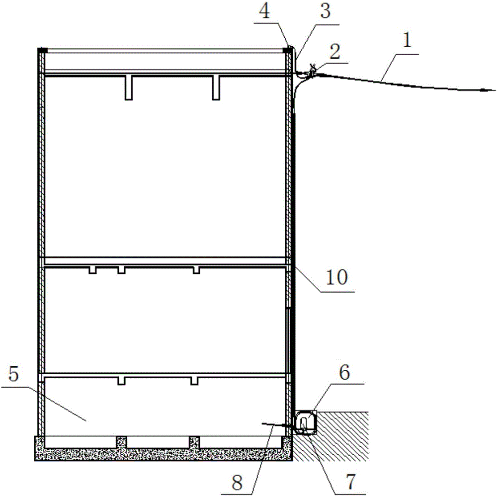
[0037] see Figure 1 to Figure 3 , the method for leading the OPGW optical cable of the power distribution building into the station provided by this embodiment includes the following steps:

[0038] S1: Fix the OPGW optical cable 1 on the outer wall through the tension string 2, and connect the tension string ground wire 3 of the tension string 2 to the ground wire 4 of the power distribution building on the roof;

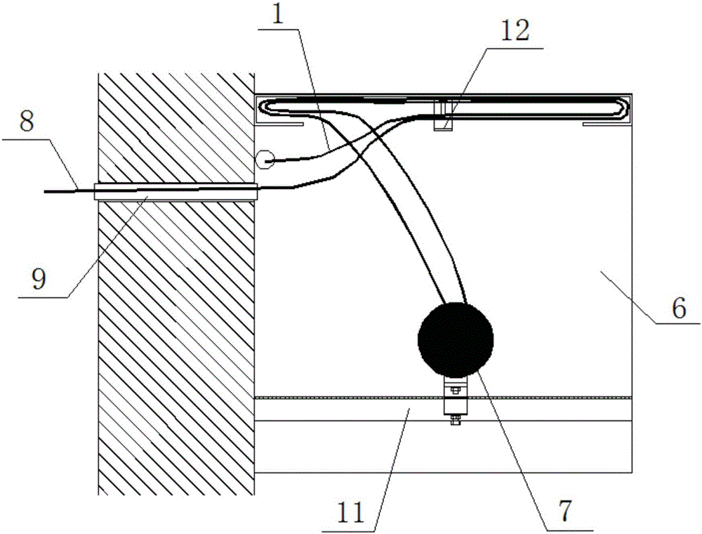
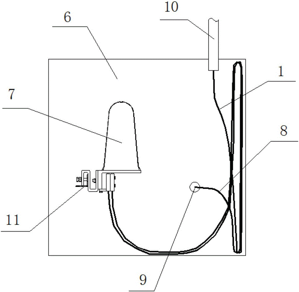
[0039] S2: Make a joint well 6 along the extension direction of the cable layer 5 on the ground close to the wall, and a joint box 7 and a guide optical cable 8 are arranged in the joint well 6;

[0040] S3: perforate the buried pipe on the wall at the joint well 6, so as to obtain the pipeline 9 connecting the inside and outside of the power distribution building;

[0041] S4: Lead the OPGW optical cable 1 down to the joint well 6 along the wall, and switch and connect with the guide optical cable 8 in the joint well 6 in the joint box 7;

[0042] S5: Distribut...


PUM


Abstract

The invention provides a distribution building OPGW optical cable down-lead inlet method which comprises the following steps: fixing an OPGW optical cable on an exterior wall by virtue of a tension string, wherein a tension string ground wire of the tension string is connected with a distribution building ground wire on the roof; making a joint well on the ground attached to the wall in the cable layer extension direction, wherein a connector box and a guide optical cable are arranged in the joint well; perforating and performing pipe laying on the wall at the joint well, so as to obtain a pipeline 9 communicated with the interior and the exterior of the distribution building; leading the OPGW optical cable down into the joint well along the wall, and performing adapter connection with the guide optical cable in the joint well in the connector box; distributing the guide optical cable in the joint well, and laying to a communication room or a secondary equipment room along the cable layer. Furthermore, adapter connection of the OPGW optical cable and the guide optical cable in the connector box in the joint well is realized, so that the optical cable layout in the station is optimized, attractive in appearance, safe and reliable. Meanwhile, the pipeline communicated with the pipeline inside and outside the distribution building is buried at the bottom of the wall, so that the overall structural performance of the house is not influenced.

Description

technical field [0001] The invention relates to the field of high-voltage transmission lines, in particular to a method for leading an OPGW optical cable in a power distribution building into a station. Background technique [0002] OPGW optical cable (Optical Fiber Composite Overhead Ground Wire) refers to placing optical fibers in the ground wire of overhead high-voltage transmission lines to form an optical fiber communication network on transmission lines. It has ordinary overhead ground wires and communication The dual functions of optical cables are therefore widely used in power systems. When the OPGW optical cable is introduced into the power distribution building, the tension string ground wire of the tension string that fixes the OPGW optical cable needs to be connected to the ground wire of the roof of the power distribution building, and the OPGW cannot directly enter the power distribution building, it must be connected to the conductor of the communication room...

Claims


Application Information

Patent Timeline
Patent Type & Authority Applications(China)
IPC IPC(8): G02B6/50
CPCG02B6/504
Inventor 张屹李铭李亨王义元孙成谢玉强曲伟崔艳昭孙少斌吕镇钱学庆
Owner STATE GRID SHANDONG ELECTRIC POWER
Why Eureka
Try Eureka