

Fixing device and image forming device
A technology for image and fixing components, which is applied to the electrical recording process using the charge pattern, equipment and instruments for the electric recording process using the charge pattern, and can solve problems such as exceeding the heat resistance temperature of the coil and achieve the effect of suppressing the temperature difference
- Summary
- Abstract
- Description
- Claims
- Application Information
AI Technical Summary
Problems solved by technology
Method used
Image

Examples
Embodiment approach 1
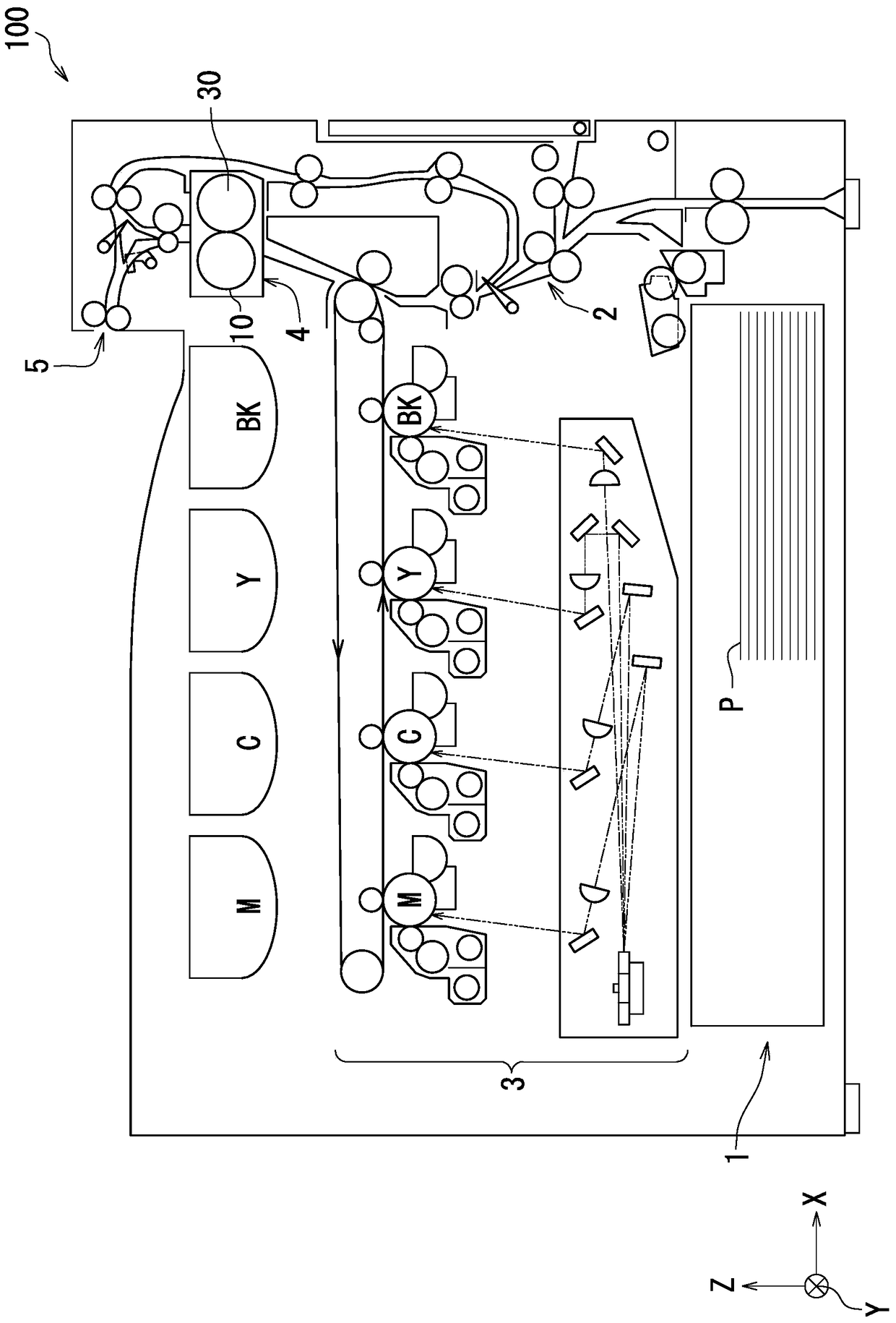
[0021] refer to figure 1 , the image forming apparatus 100 according to Embodiment 1 of the present invention will be described. figure 1 is a cross-sectional view showing the image forming apparatus 100 . Image forming apparatus 100 is a color printer. The image forming apparatus 100 includes a feeding unit 1 , a transport unit 2 , an image forming unit 3 , a fixing unit 4 as a fixing device, and a discharge unit 5 .
[0022] The feeding unit 1 stores a plurality of sheets P and sends the sheets to the conveying unit 2 . For example, the sheet P is a sheet made of paper or synthetic resin. The conveying section 2 includes several pairs of conveying rollers, and sends the sheet P to the image forming section 3 . The image forming section 3 forms an image on the sheet P by electrophotography. The transport section 2 sends the image-formed sheet P to the fixing section 4 . The fixing unit 4 heats and presses the image formed on the sheet P to fix the image on the sheet P. ...
Embodiment approach 2
[0065] refer to Figure 1 ~ Figure 3 , Figure 5 and Figure 7 ~ Figure 9 , the image forming apparatus 100 and the fixing unit 4 according to Embodiment 2 of the present invention will be described. The structure of the image forming apparatus 100 according to Embodiment 2 and figure 1 The image forming apparatus 100 according to the first embodiment shown has the same configuration, and the fixing unit 4 according to the second embodiment has the same configuration as figure 2 , image 3 and Figure 5 The structure of the fixing unit 4 according to the first embodiment shown is the same. However, the fixing unit 4 according to the second embodiment is different from the fixing unit 4 according to the first embodiment in that it includes the second guide 110A. Hereinafter, the points in which the second embodiment differs from the first embodiment will be mainly described.
[0066] Figure 7 It is an exploded perspective view showing the arched core 70 , the second g...
Embodiment approach 3
[0078] refer to Figure 10 , the image forming apparatus 100 and the fixing unit 4 according to Embodiment 3 of the present invention will be described. The configurations of the image forming apparatus 100 and the fixing unit 4 according to the third embodiment are the same as those of the image forming apparatus 100 and the fixing unit 4 according to the second embodiment. However, in the third embodiment, the second guide 110B is provided instead of the second guide 110A according to the second embodiment. Hereinafter, the points in which the third embodiment differs from the second embodiment will be mainly described.
[0079] refer to Figure 10 , the second guide 110B will be described. Figure 10 It is a sectional view showing the flow of gas for cooling the coil 52 and the second guide 110B. To simplify the drawings, in Figure 10 omitted in Figure 5 Gas A3 and Gas A4 are shown. The fixing unit 4 includes a second guide 110B instead of the second guide 110A, an...
PUM
 Abstract
Description
Claims
Application Information