Image forming apparatus

A technology of image and discharge ports, which is applied in stacking receiving devices, electric recording technology using charge patterns, equipment for electric recording technology using charge patterns, etc., can solve problems such as temperature drop, temperature difference, and high temperature, etc. Achieve the effect of suppressing temperature rise and suppressing temperature difference

Active Publication Date: 2017-12-19
RICOH KK
View PDF6 Cites 0 Cited by
  • Summary
  • Abstract
  • Description
  • Claims
  • Application Information

AI Technical Summary

Problems solved by technology

However, since the image forming apparatus having the above-mentioned suction device exhausts air from one side outside in the width direction of the paper conveyance path, in the width direction in the paper conveyance path, air is discharged from the end portion on the side where the suction device is not provided. Beginning towards the end of the side where the suction device is provided creates a temperature gradient that becomes high temperature
Then, there is a temperature difference between the ends in the width direction, and when trying to sufficiently lower the temperature of the air that becomes high temperature and is installed on the side of the suction device, the temperature is originally the lowest on the side where the suction device is not installed. The temperature will drop excessively

Method used


Image

  • Image forming apparatus
  • Image forming apparatus
  • Image forming apparatus

Examples


Embodiment Construction

[0015] Hereinafter, an embodiment of an electrophotographic copier (hereinafter simply referred to as "copier 100") will be described as an image forming apparatus to which the present invention is applied. In this embodiment, a monochrome image forming apparatus is described as an example of the copier 100 , but the present invention is also applicable to a known color image forming apparatus. In addition, although the copier 100 is a desktop compact image forming apparatus, the present invention can also be applied to a relatively large image forming apparatus placed on the floor.

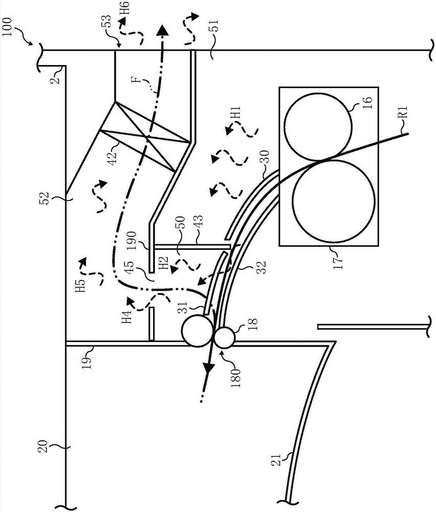
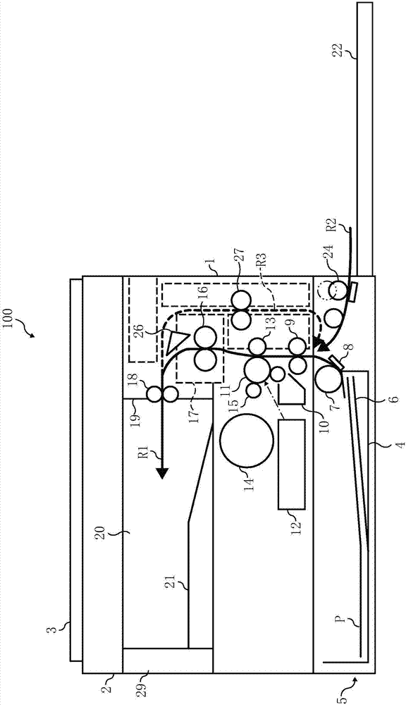
[0016] figure 2 Shown is a schematic configuration diagram of the entire copying machine 100 according to this embodiment. In the copier 100 , a document reading device 2 is provided on the upper surface of a printing unit 1 that performs image formation, and a document pressing plate 3 is provided thereon. In addition, in the lower part of the printing part 1, there is a figure 2 The paper ...


PUM


Abstract

The invention provides an image forming apparatus image which can suppress the temperature difference in the width direction of the conveyance path of the recording medium while suppressing the temperature increase of the discharge recording medium accommodating unit. The image forming apparatus includes an image forming mechanism of a fixing unit (17) for forming an image on paper, a casing (19) for receiving the image forming mechanism, a paper outlet (180) for discharging the paper for forming the image through the image forming mechanism, a discharged paper receiving part (20) for receiving the paper from the paper outlet, the discharged paper receiving part is surrounded by a wall surface portion including a wall surface portion provided with a paper outlet and is at least an in-body paper outlet having a space in which one side surface of the apparatus body is open, a copier (100) is provided with a suction fan (42) that suctions gas from an air suction hole (45) provided on the inner side of a range in which the paper can be passed in the conveyance path width direction for conveying the paper to the paper outlet to suction the air and exhaust the air to the outside of the casing.

Description

[0001] This application is a divisional application of Chinese patent application 201610277773.3 filed on April 27, 2016, entitled "Image Forming Device". technical field [0002] The present invention relates to an image forming apparatus. Background technique [0003] Conventionally, as an electrophotographic image forming apparatus, a configuration in which paper on which an image is formed by an image forming unit inside a housing is discharged from a paper discharge port to a paper discharge unit outside the housing is adopted as a paper discharge unit. It is an internal paper discharge unit provided in the body of the device main body (Patent Document 1, etc.). [0004] As an image forming apparatus using the above-mentioned internal paper discharge unit, it is generally known to provide a suction device on one side wall on the outer side in the width direction of the paper conveyance path between the fixing unit and the paper discharge port to suck the paper conveyanc...

Claims


Application Information

Patent Timeline
Patent Type & Authority Applications(China)
IPC IPC(8): G03G15/00
CPCG03G15/6552G03G15/6555B65H29/14B65H29/52B65H31/02B65H2301/5144B65H2301/5305B65H2404/6111G03G21/206B65H1/00
Inventor 小松崎宽央北川修
Owner RICOH KK
Why Eureka
Try Eureka