Manufacturing method of the rotor

A manufacturing method and rotor technology, applied to magnetic circuit rotating parts, magnetic circuit shape/style/structure, transportation and packaging, etc., can solve the problems of easy retention of cooling medium and reduction of rotor cooling efficiency, and achieve the purpose of suppressing shaft shaking, Improved cooling efficiency, efficient cooling effect

Active Publication Date: 2022-05-31
HONDA MOTOR CO LTD
View PDF9 Cites 0 Cited by
  • Summary
  • Abstract
  • Description
  • Claims
  • Application Information

AI Technical Summary

Problems solved by technology

[0006] However, in the techniques of the above-mentioned documents, there is still room for improvement in terms of allowing the cooling medium to pass smoothly through the lightening hole.
That is, in the technique of the above-mentioned document, the cooling medium deflected to the outer peripheral side of the lightening hole due to the rotation of the rotor tends to stagnate in the lightening hole.
When the cooling medium stagnated in the weight reducing hole becomes high temperature due to heat exchange with the rotor, the cooling efficiency of the rotor decreases

Method used


Image

  • Manufacturing method of the rotor
  • Manufacturing method of the rotor
  • Manufacturing method of the rotor

Examples


no. 1 approach

[0079] (rotating motor)

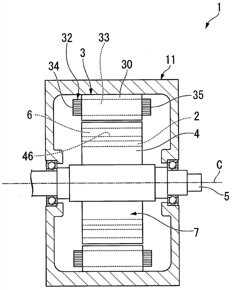
[0080] figure 1 It is a cross-sectional view showing a schematic configuration of the rotating electrical machine of the embodiment.

[0081] figure 1 The rotating electric machine 1 shown is, for example, a running motor mounted in a vehicle such as a hybrid vehicle or an electric vehicle. However, the configuration of the present invention is not limited to running motors, but can also be applied to motors for power generation, motors for other purposes, and rotating electric machines (including generators) other than vehicles.

[0082] The rotating electric machine 1 includes a housing 11 , a stator 3 and a rotor 7 .

[0083] The casing 11 accommodates the stator 3 and the rotor 7 . A cooling medium (not shown) is accommodated inside the casing 11 . The above-mentioned stator 3 is arranged inside the casing 11 in a state where a part is immersed in a cooling medium. It should be noted that, as the cooling medium, it is preferable to use ATF (...

no. 2 approach

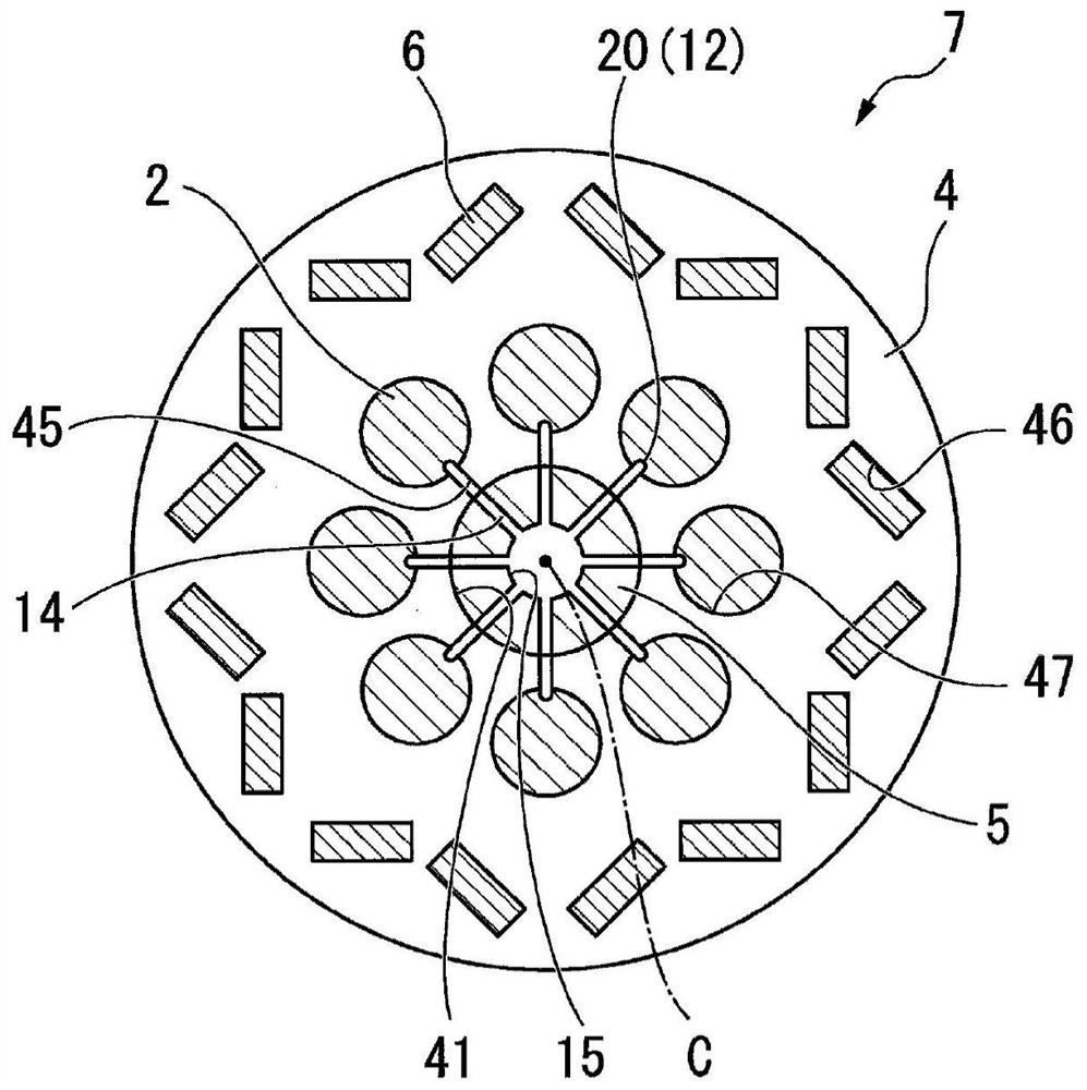
[0159] A second embodiment of the present invention will be described. Image 6 It is a side view of the rotor core of the second embodiment. in addition, Figure 7 It is an external perspective view of the sleeve of Embodiment 2, Figure 8 It is a cross-sectional view of the sleeve of the second embodiment. This embodiment differs from the above-described embodiment in that the sleeve 2 and the communicating hole 47 are formed in a triangular shape in cross-section viewed from the axial direction.

[0160] In the present embodiment, a communication hole 47 having a triangular cross section is formed in the rotor core 4 . The communication hole 47 is formed such that one corner of the triangular shape faces radially inward. A plurality of communicating holes 47 (eight in the present embodiment) are formed in the circumferential direction.

[0161] like Figure 7 and Figure 8 As shown, the outer shape of the sleeve 2 is formed in a triangular shape in cross section view...

no. 3 approach

[0173] Next, a third embodiment of the present invention will be described. Figure 10 It is a side view of the rotor core of the third embodiment. in addition, Figure 11 It is the perspective view of the appearance of the sleeve of the third embodiment, Figure 12 It is a cross-sectional view of the sleeve of the third embodiment. This embodiment differs from the above-described embodiments in that the sleeve 2 and the communicating hole 47 are formed in a trapezoidal shape in cross-section viewed from the axial direction.

[0174] In the present embodiment, the communicating hole 47 having an isosceles trapezoidal cross section is formed in the rotor core 4 . The communication hole 47 is formed so that one of the opposing bottom surfaces (the bottom surface on the short side in this embodiment) faces radially inward. A plurality of communicating holes 47 (eight in the present embodiment) are formed in the circumferential direction.

[0175] like Figure 11 and Figur...


PUM


Abstract

To provide a rotor and a rotating electrical machine capable of improving cooling efficiency. The rotor includes: an output shaft (5) configured to be rotatable around an axis (C) and having a shaft core cooling path (15) through which a cooling medium flows; and a rotor core (4) fixed to the output shaft ( 5), and has a rotor internal flow path (12), the upstream side end of the rotor internal flow path (12) communicates with the shaft core cooling path (15), and the rotor internal flow path (12) The downstream side end portion is opened on the end surface (48, 49) of the rotor core facing the direction in which the axis extends, and at least a part of the rotor internal flow path (12) has a direction extending from the upstream side end portion toward the An inclined portion (26, 27) extending radially outward in the middle of the downstream end portion.

Description

technical field [0001] The present invention relates to a rotor and a rotating electric machine. Background technique [0002] Conventionally, rotating electric machines have been used as power sources for hybrid vehicles and electric vehicles. In a rotating electric machine, magnetic attractive and repulsive forces are generated between the magnet built in the rotor core and the stator around which the coil is wound. Thus, the rotor rotates relative to the stator. [0003] In addition, the rotor generates heat due to the influence of eddy currents and the like generated in the magnets during rotation. When the magnetic force decreases due to heat generation of the magnet (so-called thermal demagnetization), the performance of the rotating electrical machine may decrease. [0004] Then, for example, Japanese Patent Application Laid-Open No. 2009-284603 discloses a structure in which a cooling medium flows through a weight-reducing hole that penetrates a rotor core in the ...

Claims


Application Information

Patent Timeline
Patent Type & Authority Patents(China)
IPC IPC(8): H02K9/19H02K1/32H02K1/22
CPCH02K9/19H02K1/32H02K1/22Y02T10/64
Inventor 竹岛彻
Owner HONDA MOTOR CO LTD
Why Eureka
Try Eureka