
An Evaluation Method for Characterizing Parameters of System-Level Single Event Effects

A single event effect and evaluation method technology, applied in the direction of electrical digital data processing, special data processing applications, instruments, etc., can solve parameter differences, cannot reflect the effect of system protection measures, and cannot give the overall impact of single event effects on the system, etc. problem, to achieve the effect of model simplification

Active Publication Date: 2019-01-15
BEIJING INST OF SPACECRAFT SYST ENG
View PDF5 Cites 0 Cited by
  • Summary
  • Abstract
  • Description
  • Claims
  • Application Information

AI Technical Summary

Problems solved by technology

However, neither the σ-LET curve characterization method of the single event effect of complex discrete logic devices nor the on-orbit single event event rate prediction method are suitable for the quantitative analysis of the single event effect of the system
This is because the system is generally composed of a large number of different units (circuit modules, electronic devices, and subsystems), and the sensitivity of each unit to single event events is different, which is manifested in the differences in LET threshold, saturation turnover cross section and single event event rate. The large difference cannot give the overall impact of the single event effect on the system, nor can it reflect the effect of the system's protective measures
At the same time, due to the differences in the tasks and functions of different systems, the impact characterization parameters of the single event effect of the system will also be different from those of the device.
Although system-level single-event effect impact characterization parameters have been proposed at home and abroad, the proposed parameters are different from different angles, and the evaluation parameters for the impact of single-event effects on the system are not yet comprehensive, and the overall impact of system-level single-event effects Insufficient quantitative evaluation and analysis of the characterization parameters

Method used


Image

  • An Evaluation Method for Characterizing Parameters of System-Level Single Event Effects
  • An Evaluation Method for Characterizing Parameters of System-Level Single Event Effects
  • An Evaluation Method for Characterizing Parameters of System-Level Single Event Effects

Examples


Embodiment 1

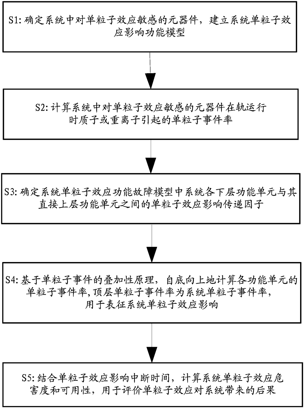
[0056] Such as figure 1 As shown, the flow chart of the evaluation method of the system-level single event effect characterization of the present invention, the specific steps are as follows:

[0057] S1: Determine the components that are sensitive to single event effects in the system, and establish a functional model of system single event effects

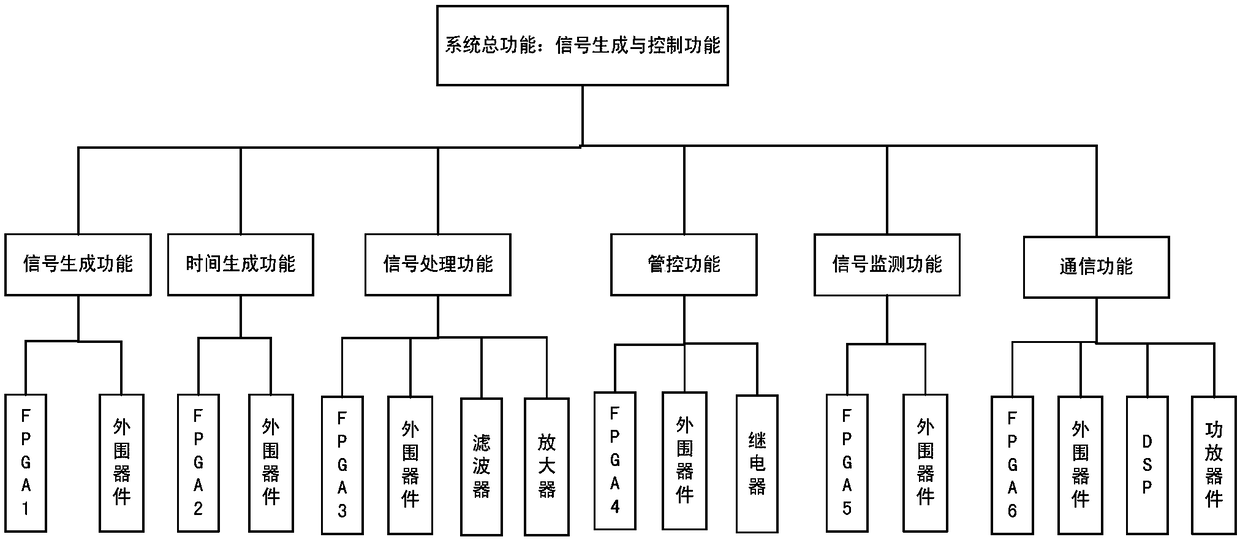
[0058] First, according to the system task requirements, determine the function of the system, and decompose the system function into several functional units from top to bottom according to the dependence and corresponding relationship between each functional unit and components, and establish a system function model with components as the bottom event .

[0059] Then, according to the physical mechanism of single event effects and the device types corresponding to various types of single event effects, determine the components that are sensitive to single event effects in the system, such as bulk silicon CMOS devices that are ...

Embodiment 2

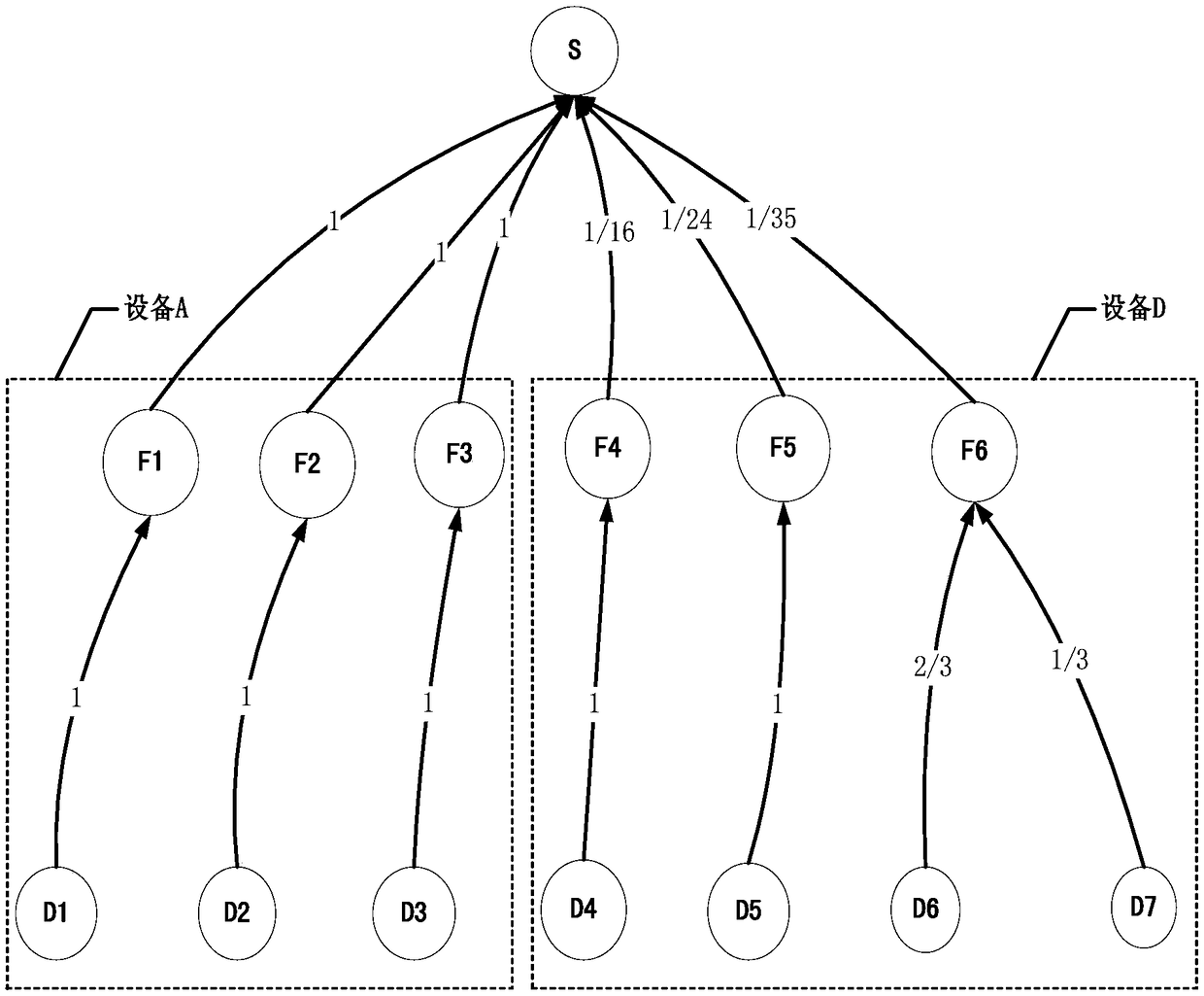
[0164] The present invention is applicable to complex whole star systems and sub-systems, and is also applicable to small systems at equipment and circuit board levels. For example, when the system is a functional unit that only realizes the communication function in Embodiment 1, the communication function is completed by FPGA6 and DSP two devices, only need to obtain the single event event rate of FPGA6 1.27E-3 times / day, DSP The single event event rate is 7.43E-7 times / day, the transmission factor of the influence of the FPGA single event failure on the communication function is 2 / 3, and the transmission factor of the influence of the DSP single event failure on the communication function is 1 / 3, according to the formula (4) That is to say, the single event rate of the system can be calculated: P=1.27E-3×2 / 3+7.43E-7×1 / 3=8.47E-4 times / day.

Embodiment 3

[0166] When the system is a more complex spacecraft system above the spacecraft signal generation and control system described in Embodiment 1, the spacecraft signal generation and control system is regarded as a function in the single event impact function model of the spacecraft system Unit, the single event event rate (SSER=8.98E-3 times / day) of the generation and control system calculated in embodiment 1 is regarded as the single event event rate of the functional unit, and is substituted into the formula (4) to calculate the upper level The single event event rate of the functional unit, and so on, and then get the single event event rate of the complex aerospace system.


PUM


Abstract

The invention discloses a system level single event effect influence representation parameter and evaluation method. The method comprises the steps that a system function model with a component as a bottom event is built, and a system single event effect influence function model is built by means of component single event sensitivity analysis; on the basis of single event effect test data, the single event rate of the sensitive component is calculated and analyzed, fault injection or a heavy ion irradiation test method or a system historical data analysis method is adopted for determining single event effect influence transfer factors between layers; on the basis of the single event superposition principle, the system single event rate is calculated; the system single event effect criticality and usability are calculated. The quantitative method is used for representing the influences of the single event effect on the system, the influence result of the system single event effect is evaluated, and the method can be used for guiding the quantization control over the system level single event effect risk.

Description

technical field [0001] The present invention relates to a method for evaluating the characterization parameters of aerospace electronic equipment and the influence of the single event effect of the whole star system, especially relates to the characterization evaluation of the influence of the single event effect of the equipment containing large-scale integrated circuits or the whole star system, which belongs to the evaluation of the single event effect of the system field. Background technique [0002] The single event effect refers to that when a single high-energy particle passes through the sensitive junction area of ​​a microelectronic component, it deposits energy and generates a sufficient amount of charges. After these charges are collected by the device electrodes, it causes abnormal changes in the logic state of the device or causes damage to the device. During the in-orbit operation of the spacecraft electronic system, it is inevitable to encounter single event ...

Claims


Application Information

Patent Timeline
Patent Type & Authority Patents(China)
IPC IPC(8): G06F17/50
CPCG06F30/367
Inventor 林益明于登云郑玉展赵海涛蔡震波张庆祥
Owner BEIJING INST OF SPACECRAFT SYST ENG
Learn More