
A card circulation switching mechanism and a card issuing machine using the mechanism

A switching mechanism and card technology, applied to computer parts, machines for issuing pre-printed tickets, ticketing equipment, etc., can solve the problems of heavy card weight, inconvenient maintenance, troublesome control, etc., to achieve convenient card installation and post-maintenance work The effect of low volume and low control module requirements

Inactive Publication Date: 2018-03-16
GUANGDONG ELECTRONICS TECH RES INST
View PDF9 Cites 0 Cited by
  • Summary
  • Abstract
  • Description
  • Claims
  • Application Information

AI Technical Summary

Problems solved by technology

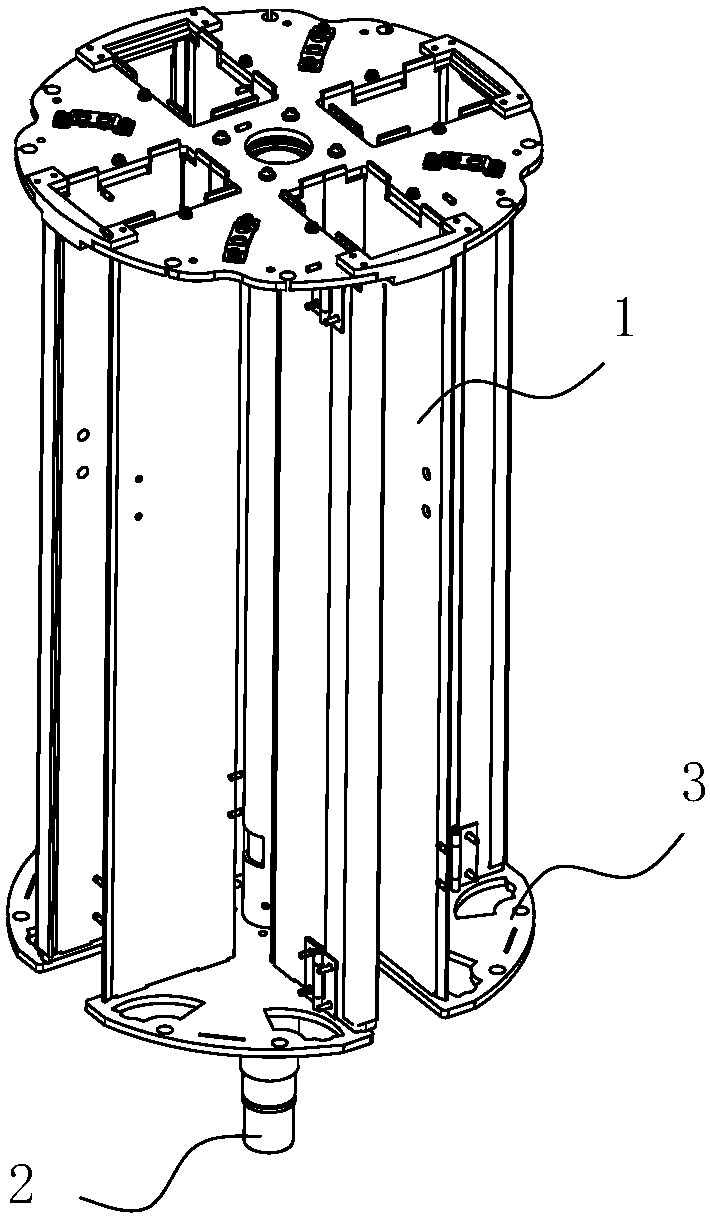
like figure 1 As shown, the card box 1 is fixed on the turntable 3, and the main rotating shaft 2 is driven by the motor to rotate the turntable 3 to complete the switching of the card box 1. In view of the fixed card output position, the turntable 3 must be rotated accurately, but because the turntable 3 And the weight of the card is relatively heavy, and the rotating mechanism needs a large-diameter main shaft 2, supporting bearings, motors, etc., the structure is complex, the cost is high, the control is troublesome, and it is inconvenient to maintain when a fault occurs

Method used


Image

  • A card circulation switching mechanism and a card issuing machine using the mechanism
  • A card circulation switching mechanism and a card issuing machine using the mechanism
  • A card circulation switching mechanism and a card issuing machine using the mechanism

Examples


Embodiment Construction

[0037] The technical solutions of the present invention will be further described below in conjunction with the accompanying drawings and through specific implementation methods.

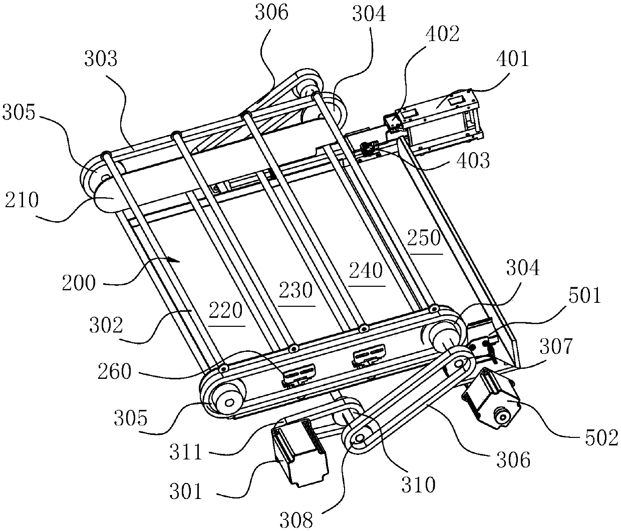
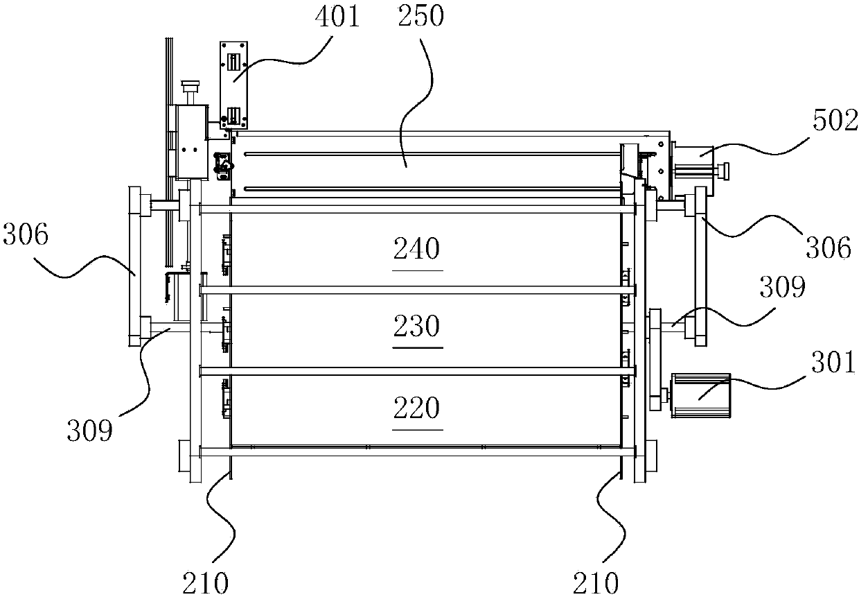
[0038] Such as Figure 2-8 As shown, in this embodiment, a card cycle switching mechanism according to the present invention includes a card tray 200 arranged horizontally, and a pusher located above the card tray 200 that is located on the first side of the card tray 200 A card feeding device that moves upwards. Several cards 100 can be vertically arranged on the card tray 200. The card feeding device and the card tray 200 jointly form a number of card storage channels, and are formed on one side of the card storage channels. The card issuing channel 250, the distance between the card storage channel and the card storing channel and between the card storing channel and the card issuing channel 250 is the same, and a card issuing component is arranged at one end of the card issuing channel 250, and ...


PUM


Abstract

The invention discloses a mechanism for switching cards cyclically, and the mechanism comprises a horizontal card tray, and a card conveying device which is located above the card tray and can push the card tray to move in a first direction. The card tray can be vertically provided with a plurality of cards, and the card conveying device and the card tray form a plurality of card storage channels. Moreover, a card sending channel is formed at a side of the plurality of card storage channels. The distance between the card storage channels is equal to the distance between the card storage channels and the card sending channel. One end of the card sending channel is provided with a card sending assembly, and the other end of the card sending channel is provided with a card feeding assembly which feeds card to the card sending assembly. The invention also discloses a card sender employing the mechanism. Because each card is arranged vertically, there is no mutual impact on the gravities of the adjacent cards, and there is no need to overcome the gravities of the cards. The card feeding assembly is simpler, and only a smaller motor is needed. A screw can complete the card feeding operation, and the motor parameters employed during circular switching are smaller. Moreover, the requirements for a control module are low.

Description

technical field [0001] The invention relates to the technical field of card receiving and receiving devices, in particular to an automatic card issuing device for expressway toll collection, in particular to a card cycle switching mechanism and a card issuing machine using the mechanism. Background technique [0002] The transportation network formed by the expressway is becoming more and more important in the modern traffic system. When the motor vehicle passes the toll station, the toll station needs to take out or recycle the issued IC card and other cards from the card receiving and receiving machine. IC card with vehicle information entered, while the expressway exit will accept the card and charge the vehicle passing fee according to the information in the card. [0003] With the increasing mileage of highways in my country, the problem of ambiguity in vehicle driving paths is becoming more and more prominent (for example: suppose there are three paths from point A to ...

Claims


Application Information

Patent Timeline
Patent Type & Authority Patents(China)
IPC IPC(8): G07B15/06G07B3/00G06K13/14
CPCG06K13/14G07B3/00G07B15/06
Inventor 翁名涛何炳林于晓丽梁柱扬王德浩曾焕聪
Owner GUANGDONG ELECTRONICS TECH RES INST
Learn More