Heat collecting plate with high energy efficiency ratio and stable work

A heat-collecting panel and energy-efficiency ratio technology, applied in the field of solar heat-collecting panel manufacturing, can solve problems such as affecting the heat absorption of the panel surface, hindering the return of the compressor, and reducing the energy-efficiency ratio, so as to achieve sufficient heat absorption, reduce operating resistance, and extend the The effect of service life

Pending Publication Date: 2020-06-02
浙江柿子新能源科技有限公司
View PDF0 Cites 3 Cited by
  • Summary
  • Abstract
  • Description
  • Claims
  • Application Information

AI Technical Summary

Problems solved by technology

[0003] 1. The bottom-in and top-out supply and return method makes the bottom or edge of the heat collecting plate have dead angles, and the working fluid in the oil-liquid mixture cannot enter this area during work, which wastes the evaporation area of ​​the heat collecting plate, affects the heat absorption of the plate surface and affects the energy efficiency of the system ;The vaporized gaseous working medium will accumulate in the dead corner, destroying the overall pressure balance of the heat collecting plate, and causing local swelling and cracking of the heat collecting plate in severe cases
[0004] 2. The oil and the working medium are in a state of mutual solubility. As the temperature of the working medium drops, the solubility of the oil will be greatly reduced. The working medium will be separated from the oil in the heat collecting plate, and the separated oil cannot evaporate. natural sinking
The milder phase change will lead to the weakening of the gaseous working medium activity, further weakening its oil return ability, or even completely losing the oil return. After working in extremely cold conditions for a long time, the lubricating oil will continue to accumulate in ( In the flow channel at the bottom or edge of the heat collecting plate, the compressor will eventually fail due to lack of lubricating oil and cannot work
[0006] 3. In addition, when the ambient temperature in extremely cold working conditions is close to the boiling point of the working medium, on the one hand, the liquid working medium cannot get enough heat and cannot be completely evaporated into a gaseous working medium. The accumulation at the bottom, and even the entire plate surface will become a "liquid storage tank", causing the working system where the heat collecting plate is located to appear to be "lack of working fluid", causing high temperature in the compressor in the system, and in severe cases, the compressor will be burned
[0007] 4. On the other hand, the liquid working medium enters from the lower part of the heat collecting plate. Since it does not get enough heat to evaporate into a gaseous state, the liquid working medium is greatly affected by gravity at this time, which will hinder the compressor from returning to air, which greatly increases the system's heat accumulation. The resistance of the hot plate part increases the power consumption of the compressor and reduces the energy efficiency ratio

Method used


Image

  • Heat collecting plate with high energy efficiency ratio and stable work
  • Heat collecting plate with high energy efficiency ratio and stable work
  • Heat collecting plate with high energy efficiency ratio and stable work

Examples


Embodiment 1

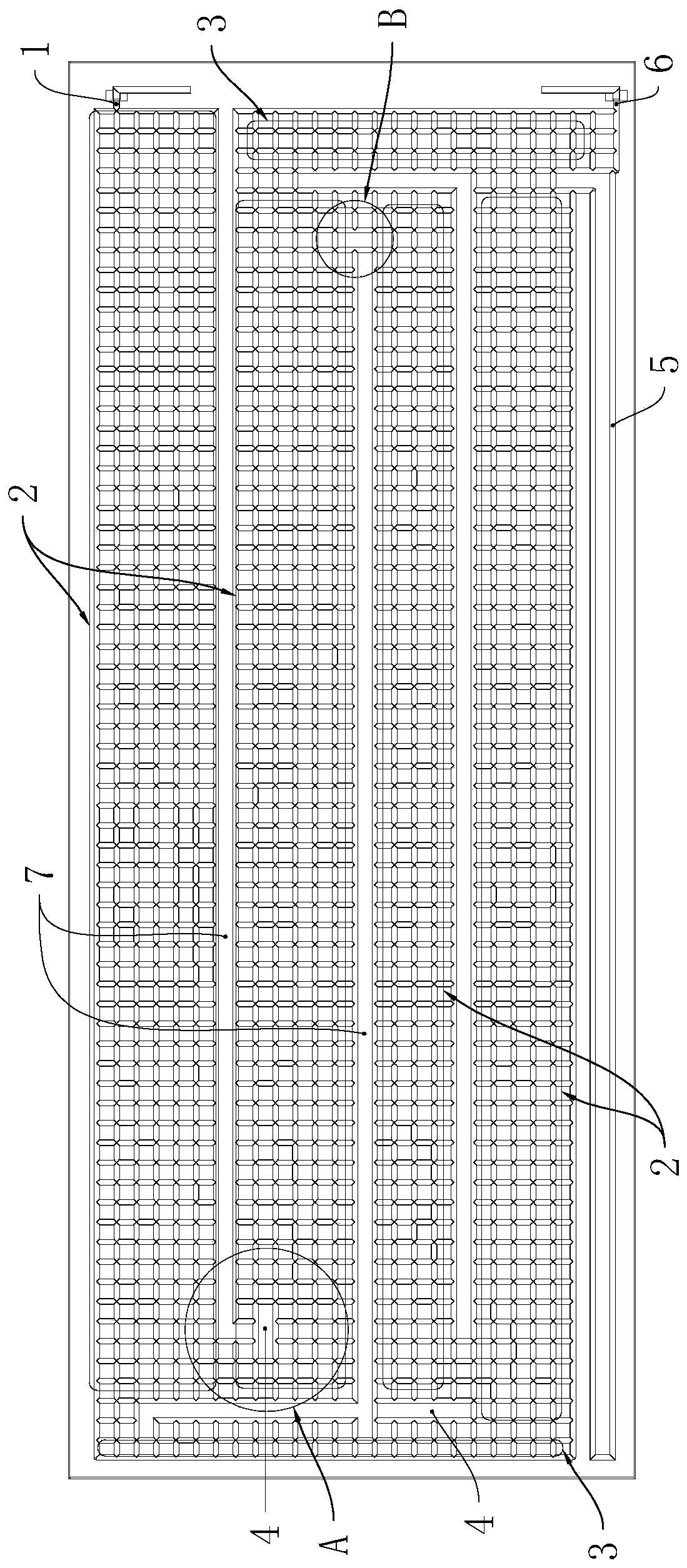
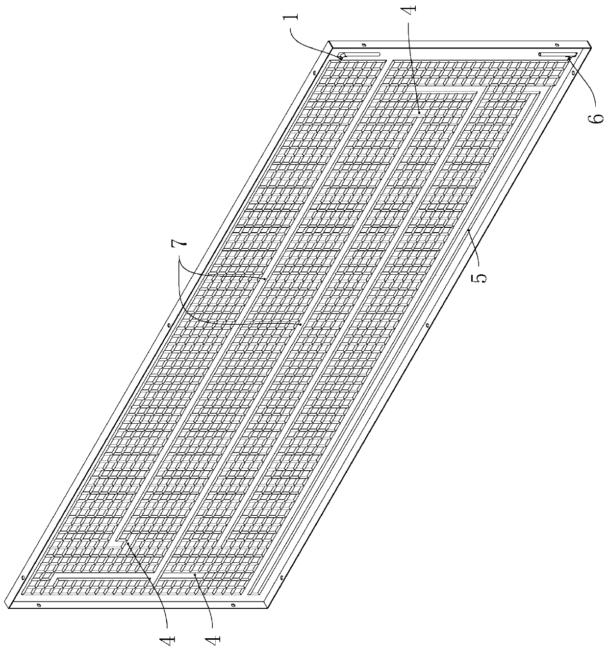
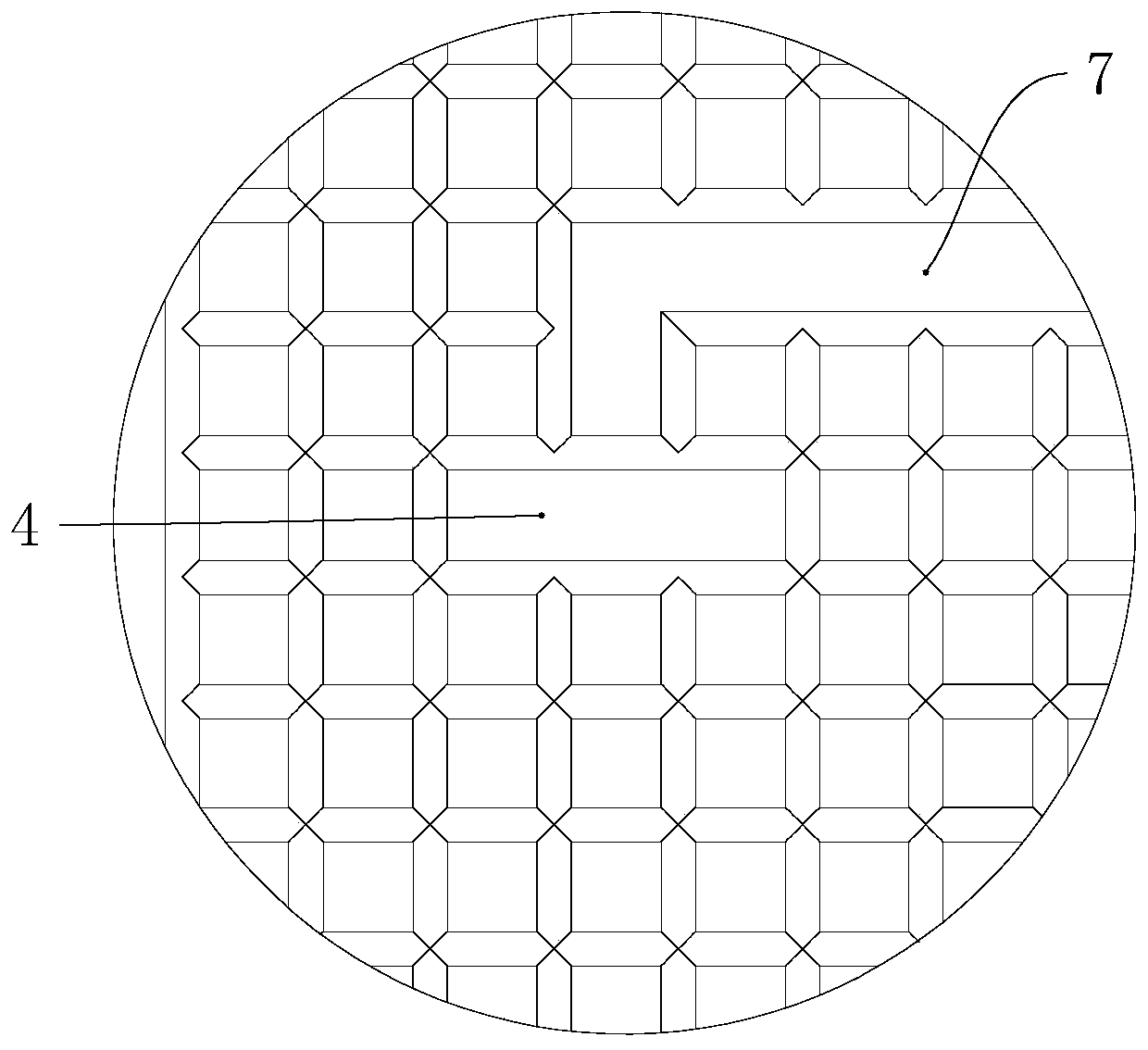
[0028] Embodiment 1: as figure 1 and figure 2 As shown, it shows a heat collecting plate with high energy efficiency ratio and stable operation, which includes a panel body, and the panel body is provided with grid-like distribution of working medium channels. In this embodiment, the panel is rectangular, and the working The flow channel is composed of two groups of pipes that criss-cross and communicate with each other, one group of pipes is arranged horizontally, and the other group of pipes is arranged vertically. When the panel body is in use, it is installed vertically on the outer surface of the wall or inclined in the open air through a fixing frame (in addition, the panel can also be curved according to the needs of the actual situation).

[0029] The panel body is also provided with a working medium inlet 1 and a working medium outlet 6 respectively connected to the working medium flow channel, the working medium inlet 1 is located at the top of the working medium f...

Embodiment 2

[0036] Embodiment 2: as Figure 5 As shown, another embodiment of a heat collecting plate with high energy efficiency ratio and stable operation is shown. The main difference between embodiment 2 and embodiment 1 is that the evaporation zone 2 in embodiment 2 is equipped with a The extension part 8 for conveying the liquid working fluid in the horizontal direction. The extension part 8 is arranged horizontally, and several extension parts 8 are distributed step by step in the evaporation area 2 . During operation, the liquid working medium enters from the side of the evaporation zone 2 and spreads horizontally when passing through several extension flow parts 8 . The remaining features and structures are the same as those in Embodiment 1, and will not be described in detail here.


PUM


Abstract

The invention relates to the field of solar panel manufacturing, and provides a heat collecting plate with high energy efficiency ratio and stable work. The heat collecting plate can be used for solving the problems that a working medium in an existing heat collecting plate is in a bottom-in and top-out working mode, the heat absorption is uneven, the energy efficiency ratio is low, and the oil return is unsmooth. The heat collecting plate with high energy efficiency ratio and stable work comprises a panel body, a working medium runner is arranged in the panel body, the panel body is further provided with a working medium inlet and a working medium outlet which are connected with the working medium runner, the working medium inlet is located in the top of the working medium runner, and theworking medium outlet is located in the bottom of the runner; and the heat absorption effect is balanced, the energy efficiency ratio is high, and oil return is smooth.

Description

technical field [0001] The invention relates to the field of manufacturing solar heat collecting panels, in particular to a heat collecting panel with high energy efficiency ratio and stable operation. Background technique [0002] The heat collecting plate is an important part of the solar heteropolymer heating equipment. Its interior is covered with oil flow channels. When the working fluid flows through the flow channels, the phase state changes (liquid and gas) to absorb the heat in the environment and realize The purpose of improving energy efficiency. In the existing layout structure of the heat collecting plate, the flow channel usually adopts the way of oil liquid (the liquid in which is the working medium, referred to as the working medium; the oil is lubricating oil, used to lubricate the compressor) from the bottom to the top. It was found that the current heat collecting board has the following defects: [0003] 1. The bottom-in and top-out supply and return me...

Claims


Application Information

Patent Timeline
Patent Type & Authority Applications(China)
IPC IPC(8): F24S10/95F24S70/60
CPCF24S10/95F24S70/60F24S2070/62Y02E10/44
Inventor 唐玉敏沈雁茜
Owner 浙江柿子新能源科技有限公司
Why Eureka
Try Eureka