
A linear eddy current braking device and a linear carrying device

A technology of eddy current braking and linear electric, which is applied in the direction of asynchronous induction clutch/brake, etc., can solve the problems of rapid reduction and limitation of braking force, achieve large braking force, low noise, and improve braking effect

Active Publication Date: 2018-08-31
CHENGDU MAOYUAN TECH
View PDF4 Cites 0 Cited by
  • Summary
  • Abstract
  • Description
  • Claims
  • Application Information

AI Technical Summary

Problems solved by technology

[0005] The object of the present invention is to propose a linear eddy current braking device for linear motion braking and the application of the linear eddy current brake to solve the above-mentioned shortcomings of the limited power of the eddy current brake and the rapid decrease of the braking force as the speed decreases. The linear carrying device of the braking device adopts segmented materials and a comb-shaped structure eddy current braking device, so that the eddy current caused by the weakening of the speed of the mover after braking can always maintain a large level, thereby continuously providing a large braking force

Method used


Image

  • A linear eddy current braking device and a linear carrying device
  • A linear eddy current braking device and a linear carrying device
  • A linear eddy current braking device and a linear carrying device

Examples


Embodiment Construction

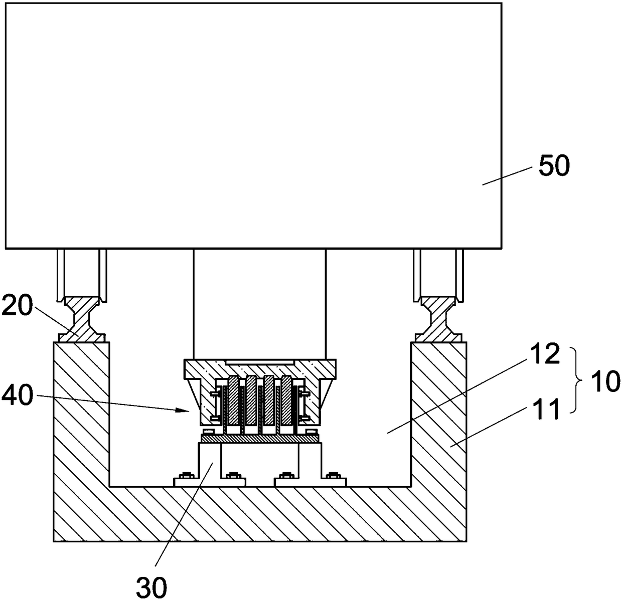
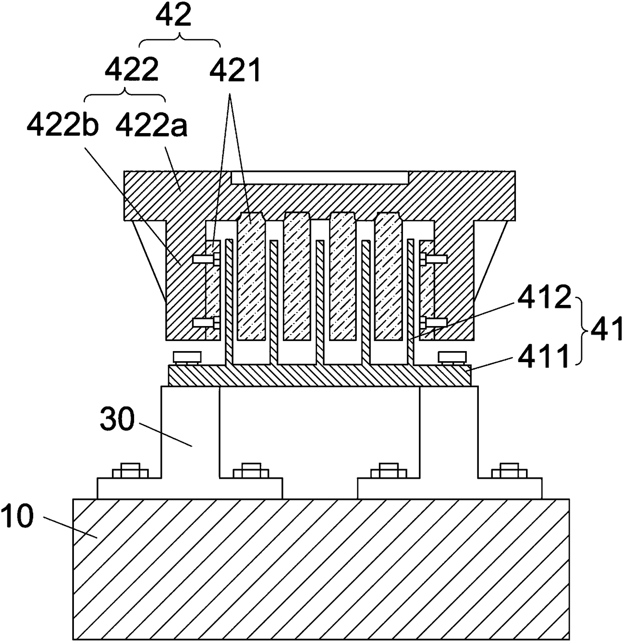
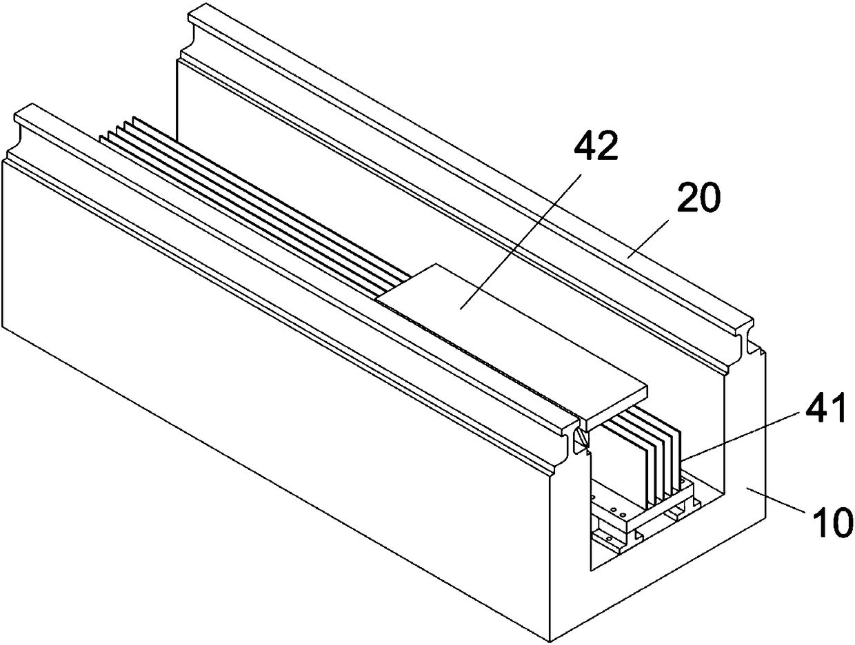
[0032] refer to Figure 1-7 , the linear eddy current braking device 40 of the present invention includes a stator 41 and a mover 42 .

[0033] The stator 41 includes a base plate 411 and a number of conductor pieces 412 arranged on the base plate 411 at equal intervals along the width direction of the base plate 411. The conductor pieces 412 are multi-stage structures made of materials with different resistivities, and are arranged along the braking direction. , the resistivity of the conductor sheet 412 decreases sequentially.

[0034] The mover 42 includes a connecting seat 422 and a number of permanent magnets 421 arranged at equal intervals along the width direction of the connecting seat 422 arranged on the connecting seat 422. The permanent magnets 421 distributed on both sides have a thickness of 421 and are distributed between the two sides. 1 / 2 of the thickness of the permanent magnets 421, and the number of the permanent magnets 421 is one more than the number of t...


PUM


Abstract

The invention discloses a linear current vortex brake apparatus and a linear carrying apparatus. The linear current vortex brake apparatus includes a stator and a mover, wherein the stator includes a substrate and a plurality of conductor sheets which are arranged on the substrate at uniform intervals in the width direction of the substrate; each conductor sheet utilizes a multi-segment structure made of materials with different resistivity; in the brake direction, the resistivity of each conductor sheet is successively reduced in the brake direction; the mover includes a connecting base and a plurality of permanent magnets which are arranged on the connecting base at uniform intervals in the width direction of the connecting base; the thickness of the permanent magnets at two side edges is a half of the thickness of the permanent magnets between the two side edges; the quantity of the permanent magnets is one more than the quantity of the conductor sheets; and the conductor sheets of the stator and the permanent magnets of the mover are respectively inserted into the mutual gaps. For the linear current vortex brake apparatus and the linear carrying apparatus, as a vortex brake apparatus which is made of segmented materials and uses a comb structure is utilized, stronger braking force can be continuously provided.

Description

technical field [0001] The invention relates to a linear electric eddy current braking device and a linear carrying device using the linear electric eddy current braking device. The linear electric eddy current braking device is used for rapid braking of high-speed linear moving objects. Background technique [0002] Traditional linear motion braking methods mainly include mechanical and electromagnetic. [0003] Mechanical braking includes elastic rope braking or hydraulic friction braking, etc. The braking principle is simple and the effect is safe and reliable, but it will cause damage to the braking device, large vibration shock and loud noise during the braking process; [0004] Electromagnetic braking uses electromagnetic methods to convert kinetic energy into electrical energy for power generation. Two types of methods are commonly used. One is to let the linear motor itself enter its electric braking state, and the generated electric energy can be flexibly disposed o...

Claims


Application Information

Patent Timeline
Patent Type & Authority Patents(China)
IPC IPC(8): H02K49/04
CPCH02K49/04
Inventor 王远波陆可郭冀岭张霆张松王家璐
Owner CHENGDU MAOYUAN TECH
Learn More