Recovery Circuit for Improving Temperature Instability of Negative Bias Voltage in Digitally Controlled Oscillating Circuit
A digitally controlled oscillation and negative bias temperature technology, applied in logic circuits, electrical components, reliability improvement and modification, etc., can solve the problem of affecting circuit performance, reducing the accuracy of the output frequency of digitally controlled oscillating circuits, affecting the delay time of PMOS transistors and Service life and other issues, to achieve the effect of suppressing negative drift, enhancing performance, and high practical value
- Summary
- Abstract
- Description
- Claims
- Application Information
AI Technical Summary
Problems solved by technology
Method used
Image
Examples
Embodiment 1
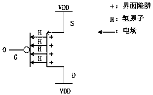
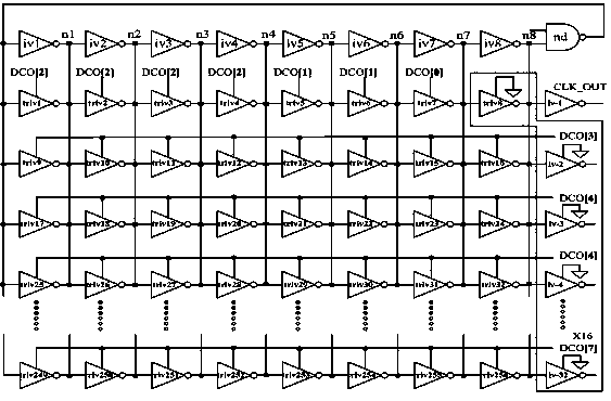
[0037] see image 3 As shown, a recovery circuit for improving the temperature instability of the negative bias voltage of the digital control oscillator circuit, including a digital control oscillator circuit and an NBTI effect recovery unit;
[0038] The digitally controlled oscillating circuit includes a first NAND gate ND1, 8 inverters iv1, iv2, iv3, ..., iv8, and 32 three-state gate inverters iv-1, iv-2, iv-3, ... , iv-32 and 256 tri-state inverters triv1, triv2, ..., triv256;
[0039] 8 said inverters iv1, iv2, iv3, ..., iv8 are connected in series, the output end of the eighth said inverter iv8 is connected to an input end of said first NAND gate ND1, said first NAND The output terminal of the non-gate ND1 is connected to the input terminal of the first inverter iv1 to jointly form a ring oscillation circuit;
[0040] 8 said inverters iv1, iv2, iv2, ..., iv8 are respectively connected in parallel with 32 said tri-state inverters to form a tri-state inverter array with...
Embodiment 2
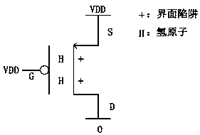
[0050] see Figure 4 As shown, a recovery circuit for improving the temperature instability of the negative bias voltage of the digital control oscillator circuit, including a digital control oscillator circuit and an NBTI effect recovery unit;
[0051] The digitally controlled oscillating circuit includes a first NAND gate ND1, 8 inverters iv1, iv2, iv3, ..., iv8, and 32 three-state gate inverters iv-1, iv-2, iv-3, ... , iv-32 and 256 tri-state inverters triv1, triv2, ..., triv256;
[0052] 8 said inverters iv1, iv2, iv3, ..., iv8 are connected in series, the output end of the eighth said inverter iv8 is connected to an input end of said first NAND gate ND1, said first NAND The output terminal of the non-gate ND1 is connected to the input terminal of the first inverter iv1 to jointly form a ring oscillation circuit;
[0053] 8 said inverters iv1, iv2, iv2, ..., iv8 are respectively connected in parallel with 32 said tri-state inverters to form a tri-state inverter array wit...
PUM
 Abstract
Description
Claims
Application Information
 - R&D
- Intellectual Property
- Life Sciences
- Materials
- Tech Scout
- Unparalleled Data Quality
- Higher Quality Content
- 60% Fewer Hallucinations
Browse by: Latest US Patents, China's latest patents, Technical Efficacy Thesaurus, Application Domain, Technology Topic, Popular Technical Reports.
© 2025 PatSnap. All rights reserved.Legal|Privacy policy|Modern Slavery Act Transparency Statement|Sitemap|About US| Contact US: help@patsnap.com


