Antenna tuning circuit and mobile terminal

A technology for antenna tuning and mobile terminals, applied in electrical components, transmission systems, etc., can solve problems such as radiation spurs, and achieve the effect of solving radiation spurs

Inactive Publication Date: 2016-08-24
GUANGDONG OPPO MOBILE TELECOMM CORP LTD
View PDF3 Cites 37 Cited by
  • Summary
  • Abstract
  • Description
  • Claims
  • Application Information

AI Technical Summary

Problems solved by technology

[0005] The embodiment of the present invention provides an antenna tuning circuit and a mobile terminal, so as to avoid t...

Method used


Image

  • Antenna tuning circuit and mobile terminal
  • Antenna tuning circuit and mobile terminal
  • Antenna tuning circuit and mobile terminal

Examples


Embodiment 1

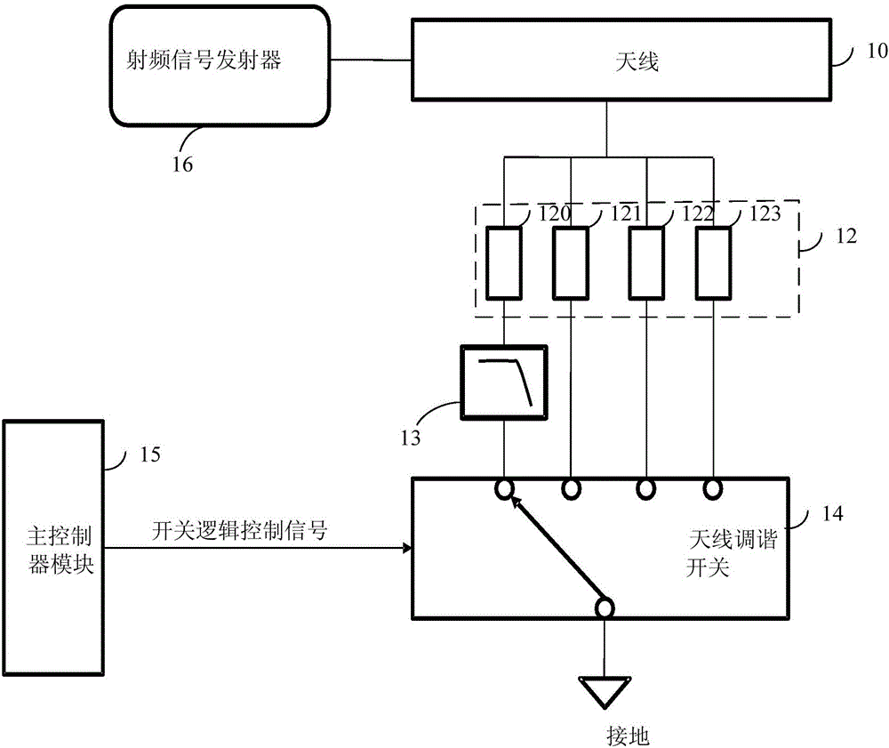
[0019] figure 1 For the schematic diagram of the antenna tuning circuit provided by Embodiment 1 of the present invention, see figure 1 , the antenna tuning circuit includes: an antenna 10 and a frequency band matching circuit 12; wherein, the frequency band matching circuit 12 is connected to the antenna 10 and the antenna tuning switch 14 respectively.

[0020] Specifically, as shown in the figure, the radio frequency signal transmitter 16 of the mobile terminal is connected and fixed to the antenna 10 as the original signal source. Generally, the frequency band of the radio frequency signal transmitted by the radio frequency signal transmitter 16 of the mobile terminal is divided into any one or any combination of 850 / 900 / 1800 / 1900 MHz and the like. The above values ​​represent that the mobile terminal can automatically switch frequencies within this frequency range according to network coverage conditions to ensure the best use effect.

[0021] Wherein, the antenna 10 is...

Embodiment 2

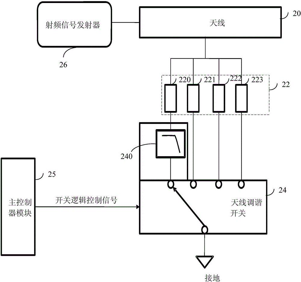
[0029] figure 2 It is a schematic diagram of an antenna tuning circuit provided in Embodiment 2 of the present invention. The antenna tuning circuit is based on the foregoing Embodiment 1, and a low-pass filter is built into the antenna tuning switch.

[0030] see figure 2 , the antenna tuning circuit includes: an antenna 20 and a frequency band matching circuit 22; wherein, the frequency band matching circuit 22 is connected to the antenna 20 and the antenna tuning switch 24 respectively. The radio frequency signal transmitter 26 of the mobile terminal is connected to the antenna 20 as an original signal source.

[0031] In the figure, the frequency band matching circuit 22 is divided into four channels, namely the GSM850 / 900 MHz frequency band matching sub-circuit 220 and other frequency band matching sub-circuits 221 , 222 , 223 . The GSM850 / 900MHz frequency band matching subcircuit 220 and other frequency band matching subcircuits 221, 222, 223 are used to select and m...

Embodiment 3

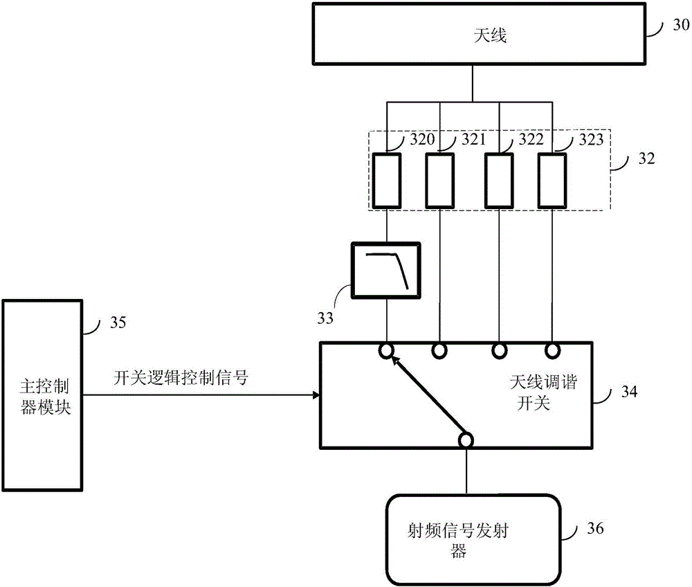
[0038] image 3It is a schematic diagram of an antenna tuning circuit provided by Embodiment 3 of the present invention. The antenna tuning circuit includes: an antenna 30 and a frequency band matching circuit 32 ; wherein the frequency band matching circuit 32 is connected to the antenna 30 and the antenna tuning switch 34 respectively.

[0039] In the figure, the radio frequency signal transmitter 36 of the mobile terminal is fixed at the common end of the antenna tuning switch 34 to provide an original signal source.

[0040] The main controller module 35 is connected to the antenna tuning switch 34 in a wired manner, and when the antenna tuning switch 34 receives the switch logic control signal sent by the main controller module 35, the path is performed according to the switch logic control signal. choose.

[0041] The frequency band matching circuit 32 is divided into four channels, which are the GSM850 / 900 MHz frequency band matching sub-circuit 320 and other frequenc...


PUM


Abstract

The embodiment of the invention discloses an antenna tuning circuit and a mobile terminal. The antenna tuning circuit comprises an antenna, a frequency band matching circuit and an antenna tuning switch, wherein the frequency band matching circuit is respectively connected with the antenna and the antenna tuning switch; the frequency band matching circuit comprises at least one frequency band matching sub circuit for selecting and matching corresponding frequency band signals from radio frequency signals transmitted by a radio frequency signal transmitter of the mobile terminal, and a low-pass filter serially connected between the frequency band matching sub circuit and the antenna tuning switch for retaining main frequency signals of a corresponding frequency band and filtering harmonics generated by the antenna tuning switch. Thus, the problem of radiated spurious emission brought by switch saturation as the antenna tuning switch generates harmonics can be avoided.

Description

technical field [0001] The embodiments of the present invention relate to the technical field of radio communication, and in particular to an antenna tuning circuit and a mobile terminal. Background technique [0002] Mobile terminals may use long-range wireless communication circuitry, such as cellular telephone circuitry, to communicate using cellular telephone frequency bands. Mobile terminals may use short-range wireless communication circuitry, such as wireless local area network communication circuitry, to handle communications with nearby devices. Mobile terminals may also have satellite navigation system receivers and other wireless circuitry. [0003] In order to meet consumer demand for miniaturized wireless devices, manufacturers have been making relentless efforts to implement wireless communication circuitry using compact structures, such as antenna assemblies. At the same time, it may be advantageous to include conductive structures, such as metal device hous...

Claims


Application Information

Patent Timeline
IPC IPC(8): H04B1/00
CPCH04B1/0057H04B1/006
Inventor 杨金胜
Owner GUANGDONG OPPO MOBILE TELECOMM CORP LTD
Why Eureka
Try Eureka