Video conference equipment support

A device support and video conferencing technology, which is applied to the legs of general furniture, reading tables, reading tables, etc., can solve problems such as unsafe, troublesome wiring, and affect the appearance, and achieve good fixation, convenient movement, and space saving. Effect

Inactive Publication Date: 2016-08-31
成都市鑫裕华科技有限公司
View PDF0 Cites 1 Cited by
  • Summary
  • Abstract
  • Description
  • Claims
  • Application Information

AI Technical Summary

Problems solved by technology

[0002] The inventor found in the process of realizing the present invention that the prior art has at least the following problems: the existing video conferencing equipment is usually equipped with a plug, but it is very troublesome when receiving the wire and needs to be retracted manually. The base will also be equipped with universal wheels. Although it is convenient to move the equipment, it does not guarantee that the equipment will not move due to vibration or uneven ground during use. Moreover, for equipment maintenance, some equipment puts the cabinet door of the device box It is installed in the front, which affects the appearance, and there is no cabinet door lock, which is very unsafe

Method used


Image

  • Video conference equipment support
  • Video conference equipment support
  • Video conference equipment support

Examples


Embodiment 1

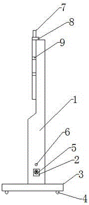
[0022] Such as figure 1 , figure 2 , image 3 As shown, a video conferencing equipment bracket includes a base 3 and a cabinet 1 installed on the base 3. The upper front of the cabinet 1 is provided with a terminal support frame 9, and the terminal support frame 9 is H-shaped or concave. The inside of the cabinet body 1 is provided with a device box, the device box is provided with an automatic take-up reel, the automatic take-up reel is connected with an electric wire, and the electric wire is connected with a power plug 5, and the side of the cabinet body 1 is provided with a take-up reel. Slot 2, the wire receiving slot 2 is provided with a wire receiving port, the diameter of the wire receiving port is smaller than the caliber of the power plug 5, and the power plug 5 is snapped into the wire receiving slot 2 through the wire receiving port, and the side of the cabinet body 1 Also be provided with take-up button 6, take-up button 6 controls the retraction of electric wi...

Embodiment 2

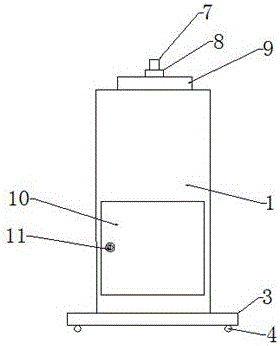
[0024] The present embodiment is further defined on the basis of the above-mentioned embodiments, the lower part of the back of the cabinet body 1 is provided with a cabinet door 10, the cabinet door 10 is provided with a cabinet door lock 11, and the cabinet door 10 faces the device box , to facilitate repair and maintenance of this equipment, the cabinet door lock 11 is to prevent other people from using the device in the device box.

[0025] Other parts of this embodiment are the same as those of the foregoing embodiment, and will not be repeated here.

Embodiment 3

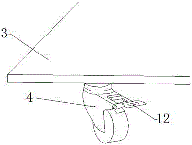
[0027] This embodiment is further defined on the basis of the above embodiments, the base 3 is rectangular, the bottom surface of the base 3 is equipped with universal wheels 4, the universal wheels 4 are arranged on the four corners of the base 3, and the universal wheels 4 The universal wheel locking device 12 is provided on the wheel 4, and the universal wheel locking device 12 can prevent the whole equipment from moving due to uneven ground when in use. The top of the cabinet body 1 is provided with a camera seat 8, and on the camera seat 8 There is a camera 7, and the upper surface area of ​​the camera seat 8 is larger than the area of ​​the top of the cabinet 1 at the corresponding position, which is more convenient for fixing the camera 7. The upper part of the front of the cabinet 1 is also provided with wiring holes, and the wiring holes are used for connecting wires. .

[0028] Other parts of this embodiment are the same as those of the foregoing embodiment, and will...


PUM


Abstract

A video conference equipment support comprises a base and a cabinet body installed on the base. A terminal support is arranged on the upper portion of the front face of the cabinet body, a device box is arranged inside the cabinet body, an automatic take-up reel is arranged inside the device box, an electric wire is connected to the automatic take-up reel, a power plug is connected to the electric wire, a take-up slot is formed in the side face of the cabinet body, a take-up opening is formed in the take-up slot, the aperture of the take-up opening is small than that of the power plug, the power plug is connected in the take-up slot through the take-up opening in a clamped mode, a take-up button is arranged on the side face of the cabinet body, a cabinet door is arranged on the lower portion of the back face of the cabinet body, a cabinet door lock is arranged on the cabinet door, universal wheels are installed on the bottom face of the base, and each universal wheel is provided with a universal wheel locking device. The video conference equipment support has the power line coming with the support, the automatic take-up reel is arranged, taking up is convenient, and the space is saved; due to the fact that the universal wheels are arranged on the base, and the universal wheel locking devices are arranged, the video conference equipment can be moved conveniently, and a good fixing effect is achieved.

Description

technical field [0001] The invention relates to the field of video equipment brackets, in particular to a video conference equipment bracket. Background technique [0002] The inventor found in the process of realizing the present invention that there are at least the following problems in the prior art: the existing video conferencing equipment is usually equipped with a plug, but it is very troublesome when receiving the wire and needs to be retracted manually. The base will also be equipped with universal wheels. Although it is convenient to move the equipment, it does not guarantee that the equipment will not move due to vibration or uneven ground during use. Moreover, for equipment maintenance, some equipment puts the cabinet door of the device box It is installed in the front, which affects the appearance, and there is no cabinet door lock, which is very unsafe. Contents of the invention [0003] The purpose of the present invention is to provide a simple structure,...

Claims


Application Information

Patent Timeline
Patent Type & Authority Applications(China)
IPC IPC(8): A47B19/10A47B91/06
CPCA47B19/10A47B91/066A47B2200/0083A47B2220/0027
Inventor 付建军
Owner 成都市鑫裕华科技有限公司
Why Eureka
Try Eureka