
Oil injection equipment

A technology of equipment and fuel injection system, which is applied in the field of automatic control, can solve the problems of increasing labor costs, increasing production efficiency, and not being able to adapt to large-scale industrial production, so as to achieve the effects of improving work efficiency, reducing quantity, and reducing production costs

Inactive Publication Date: 2016-08-31
吴宣
View PDF4 Cites 4 Cited by
  • Summary
  • Abstract
  • Description
  • Claims
  • Application Information

AI Technical Summary

Problems solved by technology

[0002] At present, due to the increase in production efficiency in the process of large-scale mechanized production, the original production mode of fuel injection equipment can no longer meet the requirements of large-scale industrial production.
[0003] In the related art, the fuel injection equipment needs to be controlled by multiple workers to complete the fuel injection operation, which makes the process of the fuel injection operation longer. If you want to increase the work efficiency of the fuel injection operation, you need to add more workers at the same time. Perform oil injection operations, which further increases labor costs

Method used


Image

  • Oil injection equipment
  • Oil injection equipment

Examples


Embodiment

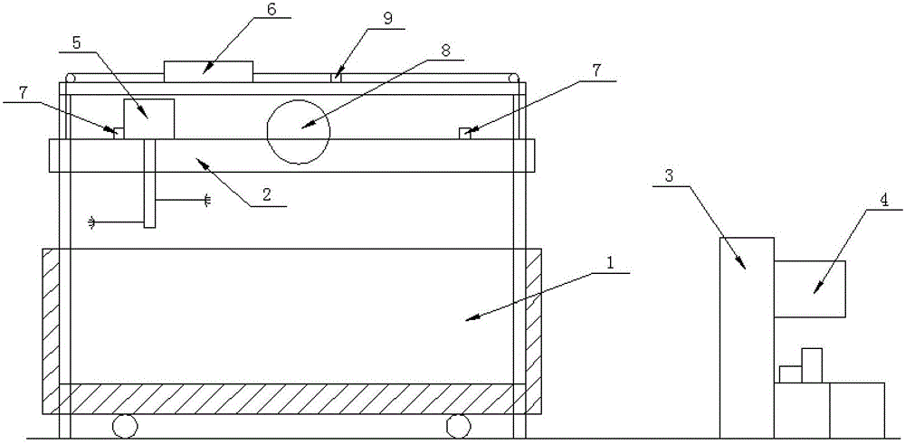
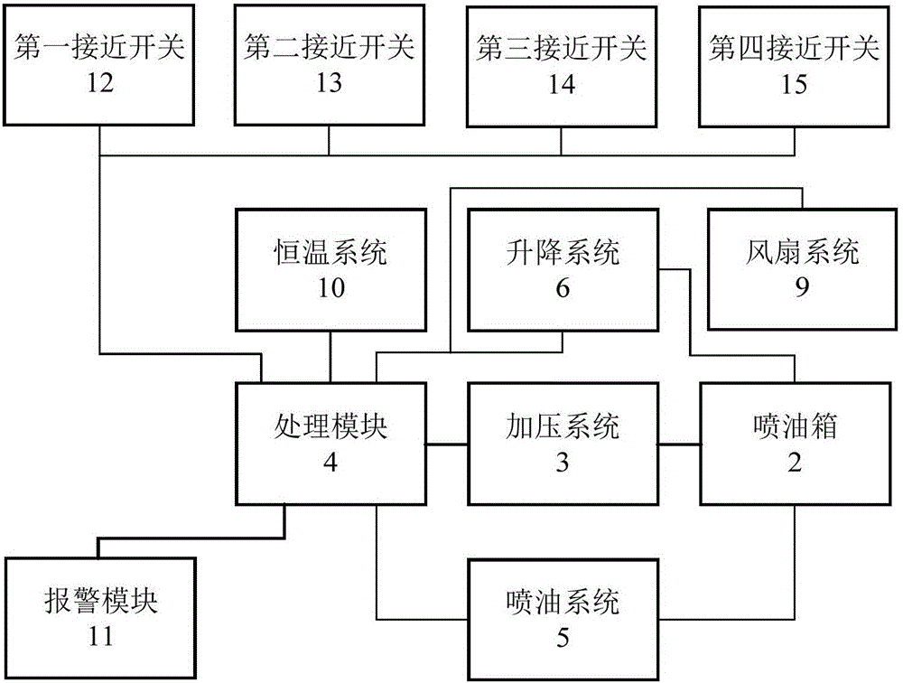
[0054] see figure 1 and figure 2 , this embodiment provides a fuel injection device, including: a support frame, a fuel injection tank 2, a fuel injection system 5, a lifting system 6 and a first positioning module 7;

[0055] The fuel injection tank 2 is connected with the lifting system 6, and is used to hold the demoulding oil to be sprayed;

[0056] The lifting system 6 is fixed on the support frame and is used to adjust the fuel injection height of the fuel injection tank 2 during the fuel injection process;

[0057] Two first positioning modules 7 are arranged on the top of the fuel injection box 2, and are used to limit the fuel injection travel area of ​​the fuel injection system 5;

[0058] The fuel injection system 5 is fixed on the top of the fuel injection box 2 and connected with the fuel injection box 2, and is used for rotating and walking in the fuel injection walking area limited by the two first positioning modules 7 during the fuel injection process.

[...


PUM


Abstract

The invention provides oil injection equipment. The oil injection equipment comprises a supporting frame, an oil injection tank, an oil injection system, a lifting system and first positioning modules; the oil injection tank is connected with the lifting system and is used for containing mold-releasing oil to be injected; the lifting system is fixed to the supporting frame and used for adjusting the oil injection height of the oil injection tank in the oil injection process; the two first positioning modules are arranged on the top of the oil injection tank and used for limiting the oil injection walking area of the oil injection system; the oil injection system is fixed to the top of the oil injection tank, is connected with the oil injection tank and is used for carrying out rotary walking oil injection on the interior of the oil injection walking area limited by the two first positioning modules in the oil injection process. According to the oil injection equipment, the production efficiency can be improved, and the production cost is reduced.

Description

technical field [0001] The invention relates to the technical field of automatic control, in particular to a fuel injection device. Background technique [0002] At present, due to the increase in production efficiency in the process of large-scale mechanized production, the original production mode of fuel injection equipment can no longer meet the requirements of large-scale industrial production. [0003] In the related art, the fuel injection equipment needs to be controlled by multiple workers to complete the fuel injection operation, which makes the process of the fuel injection operation longer. If you want to increase the work efficiency of the fuel injection operation, you need to add more workers at the same time. Carry out fuel injection operation, thus further increase labor cost. Contents of the invention [0004] In view of this, the purpose of the embodiments of the present invention is to provide an oil injection device to improve production efficiency and...

Claims


Application Information

Patent Timeline
Patent Type & Authority Applications(China)
IPC IPC(8): B05B13/04B05B12/12B05B15/00B05B15/06
CPCB05B13/041B05B12/124B05B13/0421B05B15/00B05B15/628
Inventor 吴宣王明杰
Owner 吴宣
Learn More