A punching head for flexible material cutting and its control method

A technology of flexible materials and machine heads, which is applied in metal processing and other directions, can solve problems such as slow cutting speed, high vacuum adsorption force, and product wire drawing, and achieve the effects of reducing production costs, promising market prospects, and improving work efficiency

Active Publication Date: 2018-01-02
GUANGDONG NEW RUIZHOU CNC TECH CO LTD
View PDF6 Cites 1 Cited by
  • Summary
  • Abstract
  • Description
  • Claims
  • Application Information

AI Technical Summary

Problems solved by technology

[0003] When the above-mentioned cutting method cuts the above-mentioned products, there will be certain resistance along the direction of the cutting track, which will cause the surface of the material to shift, so the cutting of the vibrating cutter head has a higher requirement for the vacuum adsorption force of the adsorption platform; when the number of material layers increases and When the thickness becomes larger, in the process of cutting multi-layer materials, the upper layer of the material is often not firmly adsorbed, which will cause the material to move during cutting, the cutting accuracy will decrease, the cutting will be deformed, and the product will have problems such as wire drawing and slow cutting speed, which are serious. Affect cutting efficiency and cutting quality

Method used


Image

  • A punching head for flexible material cutting and its control method
  • A punching head for flexible material cutting and its control method
  • A punching head for flexible material cutting and its control method

Examples


Embodiment Construction

[0032] The technical solutions of the present invention will be further described below in conjunction with the accompanying drawings and through specific implementation methods.

[0033] A punching head for cutting flexible materials such as figure 1 and 2 As shown, it includes a connecting rod 1, a blade fixing frame 11, a rotary drive mechanism, a vertical driving mechanism, an orientation guide sleeve 2 and a guide 22, and the lower end of the connecting rod 1 is provided with the blade fixing frame 11;

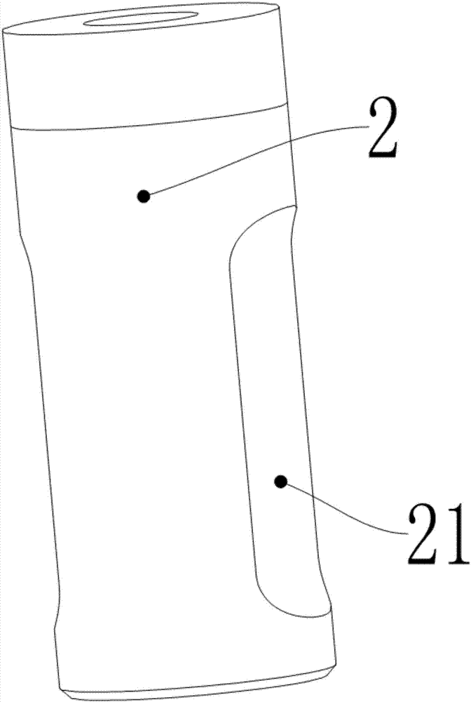
[0034] The inside of the directional guide sleeve 2 is a hollow pipe body, such as image 3 As shown, one end of the connecting rod 1 passes through the orientation guide sleeve 2 and is fixed to the blade holder 11, and the other end of the connecting rod 1 is rotatably connected to the vertical drive mechanism;

[0035] The side wall of the orientation guide sleeve 2 is provided with an orientation groove 21, and the orientation groove 21 is arranged vertically; the ...


PUM


Abstract

The invention relates to a punching head used for cutting a flexible material and a control method thereof. The punching head comprises a connecting rod, a blade fixing frame, a rotation driving mechanism, a vertical driving mechanism, a directional guide sleeve and a guide part. The blade fixing frame is arranged at the lower end of the connecting rod. A hollow pipe body is arranged in the directional guide sleeve. One end of the connecting rod penetrates through the directional guide sleeve to be fixed to the blade fixing frame, and the other end of the connecting rod is rotatably connected with the vertical driving mechanism. A directional groove is formed in the side wall of the directional guide sleeve. The guide part is fixed to the connecting rod. The punching head and a punching blade can cut the multi-layer flexible material, the requirement for the adsorption capacity of the material is low, the problems that a vibration cutter used for cutting is liable to be deformed and the multi-layer material moves during cutting are solved, the production requirement of users is met, and the work efficiency is improved. The control method achieves automation and intelligence, the completed cutting effect is good, and the market prospects are promising.

Description

technical field [0001] The invention relates to the technical field of material cutting tools, in particular to a punching head for flexible material cutting and a control method thereof. Background technique [0002] At present, the cutting method of flexible materials such as fiber materials and textiles generally adopts vibrating cutter head cutting. Vibrating cutter head cutting uses high vibration frequency (motor speed is 17200r / min, vibration amplitude is 1mm), and the blade blade is high-speed relative to the thickness direction of the material. Vibrates back and forth, and at the same time moves along the track to cut the material, such as Figure 5 shown. [0003] When the above-mentioned cutting method cuts the above-mentioned products, there will be certain resistance along the direction of the cutting track, which will cause the surface of the material to shift, so the cutting of the vibrating cutter head has a higher requirement for the vacuum adsorption force ...

Claims


Application Information

Patent Timeline
Patent Type & Authority Patents(China)
IPC IPC(8): B26F1/38B26F1/44B26D5/16B26D5/00B26D7/26
CPCB26D5/00B26D5/16B26D7/2628B26F1/38B26F1/44B26F2001/4472
Inventor 郭华忠秦少锋
Owner GUANGDONG NEW RUIZHOU CNC TECH CO LTD
Why Eureka
Try Eureka