Integrated optimization structure of stone sawing machine

A technology for optimizing the structure and stone sawing machine, which is applied in the direction of stone processing tools, stone processing equipment, work accessories, etc. The large volume and weight of the saw frame can achieve the effect of strong human design, strong practicability, and reduced manufacturing and production costs.

Inactive Publication Date: 2016-08-31
佛山市顺德区悍天睿数控机械有限公司
View PDF9 Cites 0 Cited by
  • Summary
  • Abstract
  • Description
  • Claims
  • Application Information

AI Technical Summary

Problems solved by technology

[0002] On January 29, 2011, I disclosed a transmission structure of a large-scale stone sawing machine in Chinese Patent Document No. CN202114822U, which includes a saw frame that slides up and down between the front column and the rear column. Slice / strip; the main transmission structure includes a main shaft connected to the saw frame, and the main shaft is connected to the drive motor; the main shaft is connected to the saw frame through an eccentric block and a connecting rod, and the left and right sides of the saw frame are respectively connected to the drive motor through the main shaft. The rotation speed of the two main shafts is the same; the main shaft of this structure is driven by the eccentric block and the connecting rod and the saw frame to realize the up and down movement of the saw frame. Moreover, both sides of the saw frame are connected with synchronously running main shafts, and each main shaft is driven by a drive motor. Thus, the load is shared to each drive motor; however, the saw frame of this structure is arranged between the front column and the rear column, and in actual use, due to the large volume and weight of the saw frame, there will always be a loud noise And vibration, long-term use of large noise not only affects the surrounding life, large vibration will also cause the components of the stone saw machine to loosen each other, thus affecting the environment, the overall structural stability of the stone saw machine, the stone sawing effect and service life, and even endanger the life safety of workers in severe cases

Method used


Image

  • Integrated optimization structure of stone sawing machine
  • Integrated optimization structure of stone sawing machine
  • Integrated optimization structure of stone sawing machine

Examples


Embodiment Construction

[0020] The present invention will be further described below in conjunction with the accompanying drawings and embodiments.

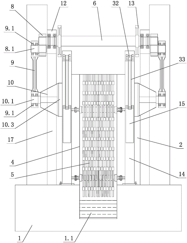
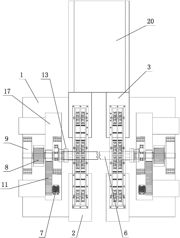
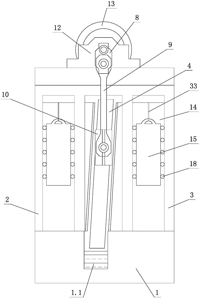
[0021] see Figure 1-Figure 5 , the integrated and optimized structure of the stone sawing machine includes a fixed base 1, and the left and right side columns 17 are arranged on the fixed base 1, and a saw frame 4 is movable between the left and right side columns 17, and a plurality of saw blades 5 are arranged on the saw frame 4 , the left and right side columns 17 are provided with a driving device for driving the saw frame 4 to move up and down. Feeding table 20, feeding table driving motor 21, feeding table driving shaft 22 and drive wheel assembly, the driving wheel assembly is arranged on the feeding table driving shaft 22, and is connected with the feeding table driving motor 21, the feeding table 20 and feeding table driving shaft 22 are matched and connected, and move forward at a slow speed and back and forth quickly between the left and ri...


PUM


Abstract

An integrated optimization structure of a stone sawing machine comprises a fixed base. A left side column and a right side column are arranged on the fixed base. A saw frame is movably arranged between the left side column and the right side column. A plurality of saw webs are arranged on the saw frame. A driving device used for driving the saw frame to move up and down in a reciprocating mode is arranged on the left side column and the right side column. The driving device comprises a spindle and a spindle driving motor. A feeding device is further arranged between the left side column and the right side column. The feeding device comprises a feeding table, a feeding table driving motor, a feeding table driving shaft and a driving wheel assembly. The driving wheel assembly is arranged on the feeding table driving shaft and is in transmission connection with the feeding table driving motor. The feeding table and the feeding table driving shaft are connected in a matched mode. The feeding table moves between the left side column and the right side column back and forth in a mode of advancing slowly and retracting rapidly through the cooperation of the feeding table driving motor and the driving wheel assembly. The integrated optimization structure has the characteristics of being simple and reasonable in structure, safe, reliable, low in production cost, high in production efficiency, high in transmission efficiency during work, low in noise, small in swing amplitude and vibration, capable of saving energy, environmentally friendly, high in practicability and the like.

Description

technical field [0001] The invention relates to an integrated optimization structure of a stone sawing machine. Background technique [0002] On January 29, 2011, I disclosed a transmission structure of a large-scale stone sawing machine in Chinese Patent Document No. CN202114822U, which includes a saw frame that slides up and down between the front column and the rear column. Slice / strip; the main transmission structure includes a main shaft connected to the saw frame, and the main shaft is connected to the drive motor; the main shaft is connected to the saw frame through an eccentric block and a connecting rod, and the left and right sides of the saw frame are respectively connected to the drive motor through the main shaft. The rotation speed of the two main shafts is the same; the main shaft of this structure is driven by the eccentric block and the connecting rod and the saw frame to realize the up and down movement of the saw frame. Moreover, both sides of the saw fram...

Claims


Application Information

Patent Timeline
Patent Type & Authority Applications(China)
IPC IPC(8): B28D1/06B28D7/04B28D7/00
CPCB28D1/06B28D1/068B28D7/00B28D7/005B28D7/04
Inventor 周金生
Owner 佛山市顺德区悍天睿数控机械有限公司
Why Eureka
Try Eureka