Self-defensive sonar locator buoy

A buoy and sonar technology, applied in buoys, positioning, sonar signal devices, etc., can solve the problems of difficult attitude maintenance, cumbersome deployment and recovery, and easy to be affected by wind and waves, so as to achieve easy deployment and recovery, and high flexibility , to overcome the effect of sea wind and surge

Active Publication Date: 2018-02-09
HARBIN ENG UNIV
View PDF4 Cites 0 Cited by
  • Summary
  • Abstract
  • Description
  • Claims
  • Application Information

AI Technical Summary

Problems solved by technology

[0003] The present invention aims to solve the problems of existing underwater acoustic positioning buoys such as poor reliability, being easily affected by wind and waves and deviating from the target point, difficulty in attitude maintenance and cumbersome deployment and recovery, and proposes a self-defense sonar positioning buoy

Method used


Image

  • Self-defensive sonar locator buoy
  • Self-defensive sonar locator buoy
  • Self-defensive sonar locator buoy

Examples


specific Embodiment approach 1

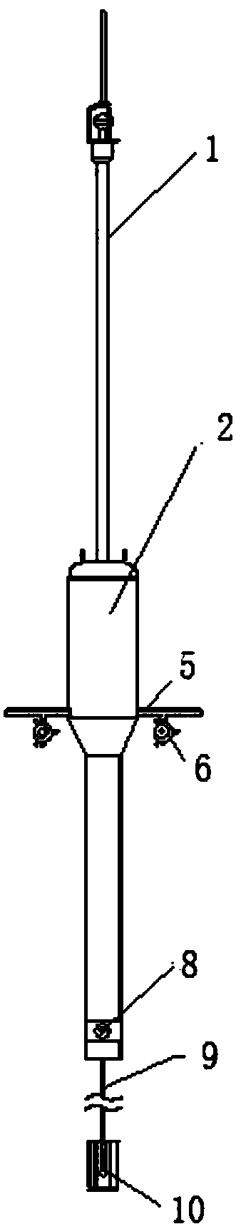
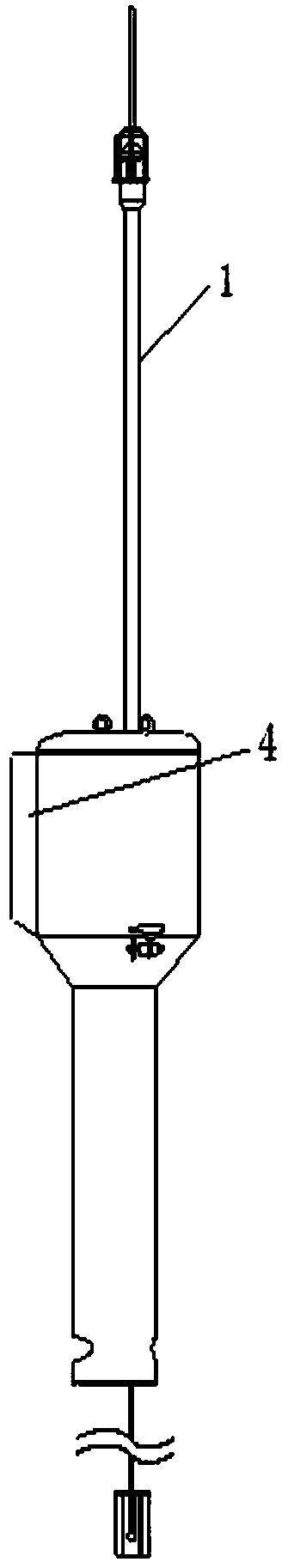
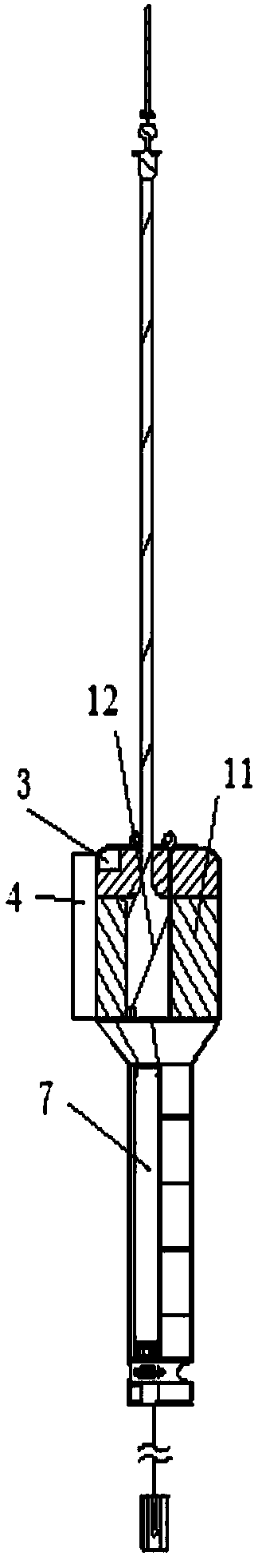
[0017] Specific implementation mode 1. Combination Figure 1 to Figure 5 Describe this embodiment, the self-defense position sonar positioning buoy described in this embodiment, it comprises antenna 1, housing 2, steering gear 3, rudder plate 4, stabilizer wing 5, main thruster 6, buoy electronic cabin 7, Channel propeller 8, cable 9, underwater acoustic transducer 10, floating body 11 and electronic cabin 12 of underwater acoustic transducer;

[0018] A floating body 11 is arranged on the outside of the electronic cabin 12 of the underwater acoustic transducer, and a steering gear 3 is arranged on the upper side of the floating body 11. The casing 2 includes two wing-shaped shells with different chord lengths, and the wing-shaped casings with long chords are fixed. On the upper side of the wing-shaped shell with small wing length, and the two wing-shaped shells are coaxially connected, the electronic cabin 12 of the underwater acoustic transducer, the floating body 11 and the...

specific Embodiment approach 2

[0024] Embodiment 2. This embodiment is a further description of the self-defense sonar positioning buoy described in Embodiment 1. Antenna 1 includes a GPS antenna, a wireless communication antenna and a beacon light;

[0025] The beacon light is used for night navigation and plays the role of warning. The positioning signal output end of the GPS antenna is connected to the positioning signal input end of the electronic cabin 12 of the underwater acoustic transducer, and the positioning signal output end of the GPS antenna is also connected to the main unit through the interface board The positioning signal input end of the control panel; the wireless signal output input end of the wireless communication antenna 41 is connected to the wireless signal input and output end of the electronic cabin 12 of the underwater acoustic transducer, and the signal input and output end of the wireless communication antenna 41 is also connected through the interface board The wireless signal ...

specific Embodiment approach 3

[0026] Specific embodiment three. This embodiment is a further description of the self-defense sonar positioning buoy described in specific embodiment one. The interface board includes four aviation plugs and a plurality of connector plugs. The three aviation plugs are connected to two The main propeller 6 is connected to the channel propeller 8; the battery charging line 17 is connected to the battery through another aviation plug on the interface board.


PUM


Abstract

The invention provides a self-position-guard sonar positioning buoy and belongs to the technical field of underwater sound communication and dynamic positioning. The self-position-guard sonar positioning buoy solves the problems that an existing underwater sound positioning buoy is poor in reliability and likely to be affected by wind and waves to deviate from a target point, a posture is difficult to keep, and arrangement and recovery are complex. A floating body is arranged on the outer side of an underwater sound transducer electronic cabin of the self-position-guard sonar positioning buoy. Shells comprise the two wing-shaped structure shells with different chord lengths. The two wing-shaped structure shells are coaxially connected. The underwater sound transducer electronic cabin, the floating body and a steering engine are all arranged in the wing-shaped structure shell with the large chord length, the floating body is arranged on the outer side of the underwater sound transducer electronic cabin, the steering engine is arranged on the upper side of the floating body and drives a rudder plate to swing, the rudder plate is arranged on the rear side of the wing-shaped structure shell with the large chord length, stabilizers are symmetrically arranged on the left side and the right side of the wing-shaped structure shell with the large chord length, and main propellers are arranged on the lower sides of the two stabilizers. The self-position-guard sonar positioning buoy is suitable for being used as a buoy.

Description

technical field [0001] The invention belongs to the technical field of underwater acoustic communication and dynamic positioning. Background technique [0002] At this stage, the underwater target positioning and tracking technology mainly uses the geometric principle of underwater acoustic positioning method. The buoy array is designed according to a certain formation, and the acoustic signal of the target is collected through the underwater acoustic transducer that is suspended, and then the data information is transmitted by radio communication technology. The data is packaged and uploaded to the mother ship, and the computer on the mother ship unpacks and stores the received data, calculates the target position by using spherical intersection technology, and monitors the working status of the buoy array. However, restricted by many factors, the existing underwater acoustic positioning buoys have problems such as single function, poor reliability, easy to be affected by w...

Claims


Application Information

Patent Timeline
Patent Type & Authority Patents(China)
IPC IPC(8): B63B22/00B63B22/16G01S5/18
CPCB63B22/00B63B22/166B63B2022/006B63B2201/18G01S5/18
Inventor 严浙平朱凤晴罗朋飞张宏瀚周佳加
Owner HARBIN ENG UNIV
Why Eureka
Try Eureka