
Joint bar construction structure and method

A construction method and reinforcement insertion technology, which are applied in building construction, construction, and building materials processing, etc., can solve the problems of complex installation structure, time-consuming installation, displacement of insertion reinforcement, failure to achieve insertion reinforcement positioning effect, etc., so as to achieve reuse. , The structure is simple, which is conducive to the effect of precise installation and connection

Active Publication Date: 2016-08-31
CHENGDU CONSTR ENG GROUP CORP
View PDF7 Cites 12 Cited by
  • Summary
  • Abstract
  • Description
  • Claims
  • Application Information

AI Technical Summary

Problems solved by technology

Although this reinforcement construction structure can avoid the deformation of steel bars to a certain extent, there are still several problems as follows: First, the fixing rods in the vertical direction of the wall and the fixing rods in the direction of the wall need to be bound one by one with the insertion reinforcement, so that the overall installation of the device The structure is complex and time-consuming, and it is inconvenient for construction personnel to operate. In addition, once the installation position of the device is incorrect, it is necessary to untie the above-mentioned binding structures one by one, which seriously delays the progress of the project; The fixing strength of the binding structure used between the direction fixing rod and the insertion bar is average. Only a part of the insertion bar is close to the vertical wall direction fixing bar. Once the concrete is over-vibrated, the binding structure is still easy to loosen, which is inevitable. The displacement and deformation of the inserted ribs will eventually cause the formed wall to move and deform, and the ideal positioning effect of the inserted ribs will not be achieved.

Method used


Image

  • Joint bar construction structure and method
  • Joint bar construction structure and method
  • Joint bar construction structure and method

Examples


Embodiment Construction

[0029] The construction structure and construction method of inserting bars in the present invention will be described in detail below through the application of the present invention in assembling integral concrete structures.

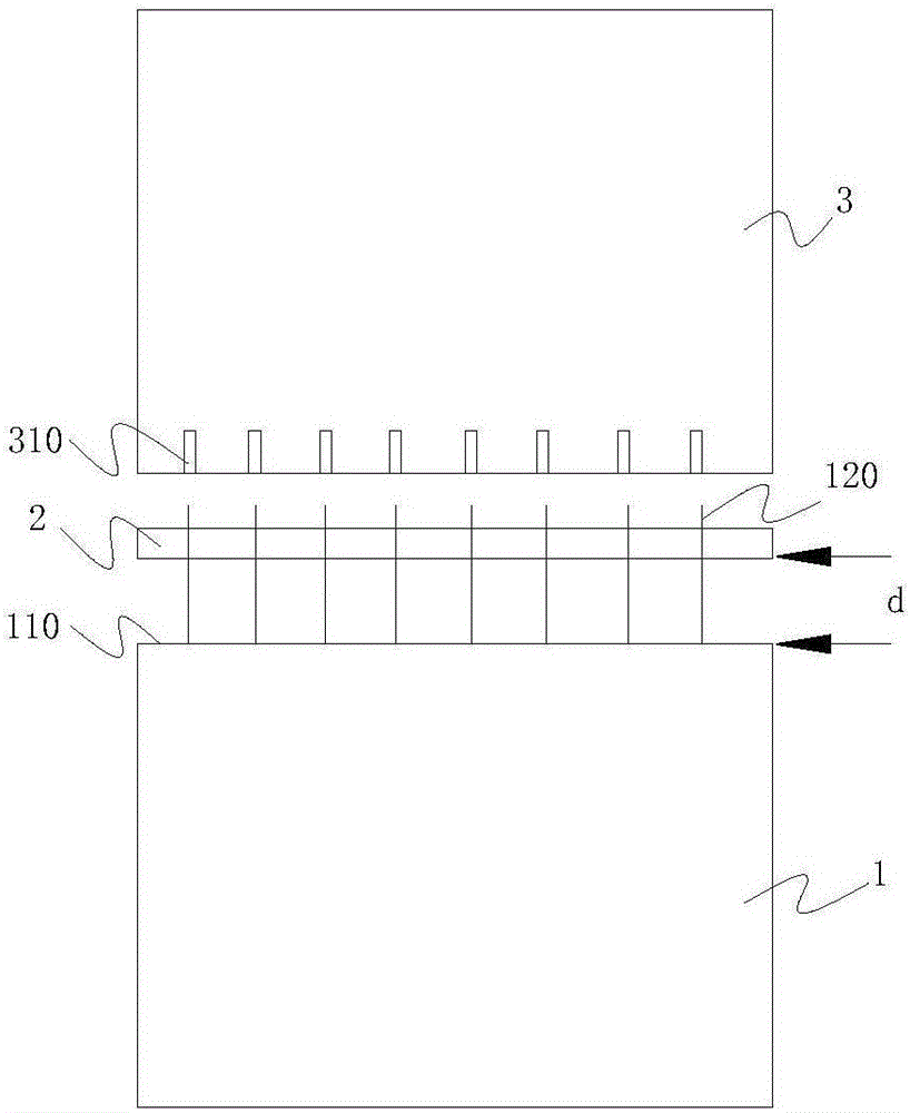
[0030] Such as figure 1 As shown, the transition layer 1 in the assembled monolithic concrete structure is subjected to reinforcement construction, the upper structure is the corresponding prefabricated component 3, and the transition layer 1 is used as the transition structure between the prefabricated component 3 and the cast-in-situ concrete wall of the lower structure. It should be further explained that after the inserting bar 120 to be positioned is inserted into the wall of the transition layer 1, the lower part of the inserting bar 120 to be positioned is generally fixed by a stirrup binding structure, and the stirrup binding structure here is different according to the specific construction situation. When there are reinforcing bars in the po...


PUM


Abstract

The invention discloses a joint bar construction structure which comprises joint bars to be positioned inserted into a wall and joint bar positioning devices arranged at the upper portions of the joint bars to be positioned. Each joint bar positioning device comprises a positioning body. Positioning holes allowing the joint bars to be positioned to be inserted in a one-to-one matched mode and a plurality of vibration channels allowing vibration bars to penetrate therein are formed in the positioning bodies. The joint bar positioning devices are arranged on or above the concrete pouring completion face. The invention further discloses a joint bar construction method adopting the joint bar construction structure. Joint bar construction is performed through the joint bar construction method adopting the joint bar construction structure, it can be ensured that joint bars below the concrete pouring completion face can be precisely installed, and therefore precise installation and connection of the wall and the upper-layer structure are promoted.

Description

technical field [0001] The invention relates to the technical field of building construction, in particular to a construction structure and method for inserting bars. Background technique [0002] Inserting reinforcement is to reserve steel bars in the lower structure to extend into the upper structure and overlap with similar members of the upper structure when the base layer or the lower structure has no similar components with the upper structure or the number of steel bars in the upper structure is more than the number of steel bars in the lower structure. rebar. Inserting bars are basically divided into basic inserting bars for vertical members and inserting bars when the variable cross-section of vertical members needs to be anchored. [0003] In the existing building structure, before the concrete pouring of the foundation or substructure, the position of the reinforcement is determined according to the designed construction blueprint, and then the reinforcement is d...

Claims


Application Information

Patent Timeline
IPC IPC(8): E04G21/12E04B1/41
CPCE04B1/41E04G21/122
Inventor 周帆田泽辉温雪飞李善继冯家荣王永斌刘刚陈忠文俊杰林裕王文珏张敏尹超罗学唐怀春
Owner CHENGDU CONSTR ENG GROUP CORP
Learn More