
Compound molecular pump using segmented structure traction level

A composite molecular pump and segmented technology, which is applied to the components of the pumping device for elastic fluids, non-variable volume pumps, non-displacement pumps, etc., can solve the problem of increased gas leakage and decreased performance of composite molecular pumps. , the increase of gap leakage, etc., to achieve the effect of improving the pumping performance

Active Publication Date: 2016-08-31
NORTHEASTERN UNIV
View PDF6 Cites 0 Cited by
  • Summary
  • Abstract
  • Description
  • Claims
  • Application Information

AI Technical Summary

Problems solved by technology

Due to the limitations of machining accuracy, assembly accuracy, centrifugal deformation and thermal deformation of the rotor, the gap between the traction stage rotor and the stator can only be appropriately increased to ensure the working reliability of the compound molecular pump, but the traction stage rotor and stator The leakage of the gap between the stators will increase, which will lead to the performance degradation of the composite molecular pump, especially when the composite molecular pump works in the transition flow state and the viscous flow state, the leakage of gas along the gap will increase, which will seriously affect the performance of the composite molecular pump. pumping performance

Method used


Image

  • Compound molecular pump using segmented structure traction level
  • Compound molecular pump using segmented structure traction level

Examples


Embodiment Construction

[0019] The present invention will be further described in detail below in conjunction with the accompanying drawings and specific embodiments.

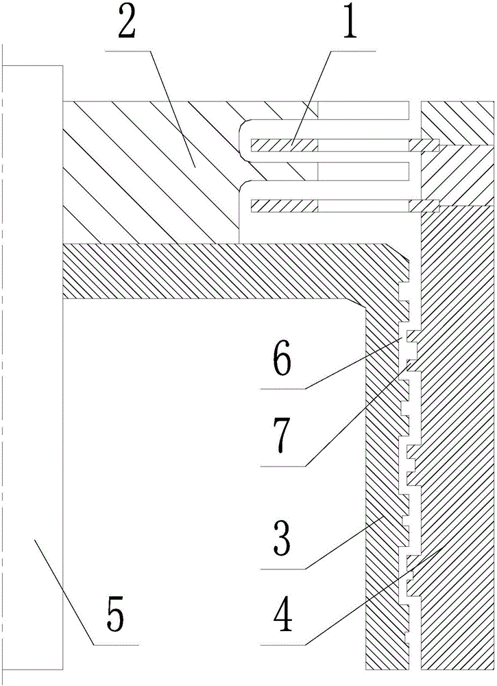
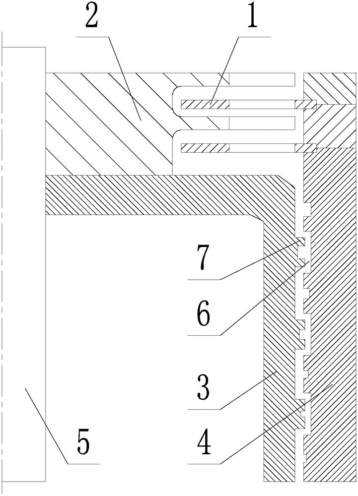
[0020] Such as figure 1 , 2 As shown, a compound molecular pump adopting a segmented traction stage includes a turbine stage, a cylindrical traction stage and a drive main shaft 5, the turbine stage includes a stator blade 1 and a moving impeller 2, and the cylindrical traction stage includes The traction rotor 3 and the stator 4, the moving impeller 2 and the traction rotor 3 are fixedly set on the driving main shaft 5, and the characteristics are: the cylindrical traction stage adopts a segmented structure, and the adjacent sections of the cylindrical traction stage An annular groove 6 and an annular boss 7 are provided, and the annular groove 6 and the annular boss 7 are arranged facing each other, and the axial centerline of the annular groove 6 and the annular boss 7 is aligned with the drive spindle The axial centerlines of 5 ...


PUM


Abstract

The invention discloses a compound molecular pump using a segmented structure traction level. The barrel-type traction level is of a segmented structure. Annular grooves and annular bosses are arranged between adjacent segments of the barrel-type traction level, and the annular grooves and the annular bosses are arranged by directly facing each other. When spiral grooves are formed in an unthreaded barrel and a traction rotor by a stator, the annular grooves are formed in the traction rotor, and the annular bosses are arranged on the stator. The traction rotor is divided into a plurality of traction rotor segments by the annular grooves. When spiral grooves are formed in the unthreaded barrel and the stator by the traction rotor, the annular grooves are formed in the stator, and the annular bosses are arranged on the traction rotor. The stator is divided into a plurality of stator segments by the annular grooves. The spiral grooves are formed in the annular bosses, the spiral direction of the spiral grooves in the annular bosses is opposite to the spiral direction of the spiral grooves in the traction rotor or the stator. In the air-exhaust direction, the number of the spiral grooves in all the traction rotor segments or stator segments and the annular bosses is set in a progressive increase mode, the groove depth of the spiral grooves is set in a progressive decrease mode, and the groove width of the spiral grooves is set in a progressive decrease mode.

Description

technical field [0001] The invention belongs to the technical field of vacuum equipment, and in particular relates to a composite molecular pump adopting segmented structure traction stages. Background technique [0002] Molecular pumps, as a kind of vacuum obtaining equipment that can obtain clean and high vacuum, have been widely used in many industrial fields. Among them, compound molecular pumps can still maintain high pumping performance in a wide pressure range. Therefore, in semiconductors, etc. It is widely used in the industry. [0003] Existing compound molecular pumps are mainly divided into two categories, one is designed by the combination of turbomolecular pump and disc traction molecular pump, that is, compound molecular pump with disc traction structure; the other is composed of turbo molecular pump and disc traction molecular pump. The barrel-type traction molecular pump is designed in combination, that is, the compound molecular pump with a barrel-type tra...

Claims


Application Information

Patent Timeline
Patent Type & Authority Applications(China)
IPC IPC(8): F04D19/04F04D29/00
CPCF04D19/042F04D29/002F04D19/044
Inventor 王晓冬巴德纯张磊张鹏飞陶继忠
Owner NORTHEASTERN UNIV
Learn More