Plate connecting structure and plate connecting method

A technology for connecting structures and panels, applied in the direction of connecting components, thin-plate connections, mechanical equipment, etc., can solve problems that affect product quality and aesthetics, uneven adjacent panels, reduce production costs, etc., to improve product quality, assembly The effect of easy operation and reduced process difficulty

Inactive Publication Date: 2016-08-31
佛山维尚家具制造有限公司
View PDF10 Cites 2 Cited by
  • Summary
  • Abstract
  • Description
  • Claims
  • Application Information

AI Technical Summary

Problems solved by technology

However, these connection methods have high requirements on the hole processing, and the hole position cannot be deviated, otherwise there will be deviations after the plates are connected, resulting in problems such as unevenness of adjacent plates or gaps between adjacent plates, which will affect Product quality and aesthetics may even lead to defective products and scrapped boards, which is not conducive to reducing production costs

Method used


Image

  • Plate connecting structure and plate connecting method
  • Plate connecting structure and plate connecting method
  • Plate connecting structure and plate connecting method

Examples


Embodiment 1

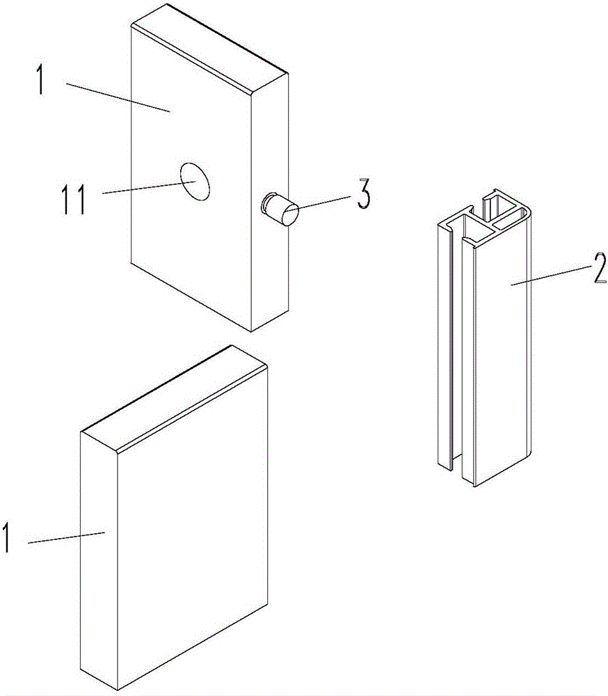
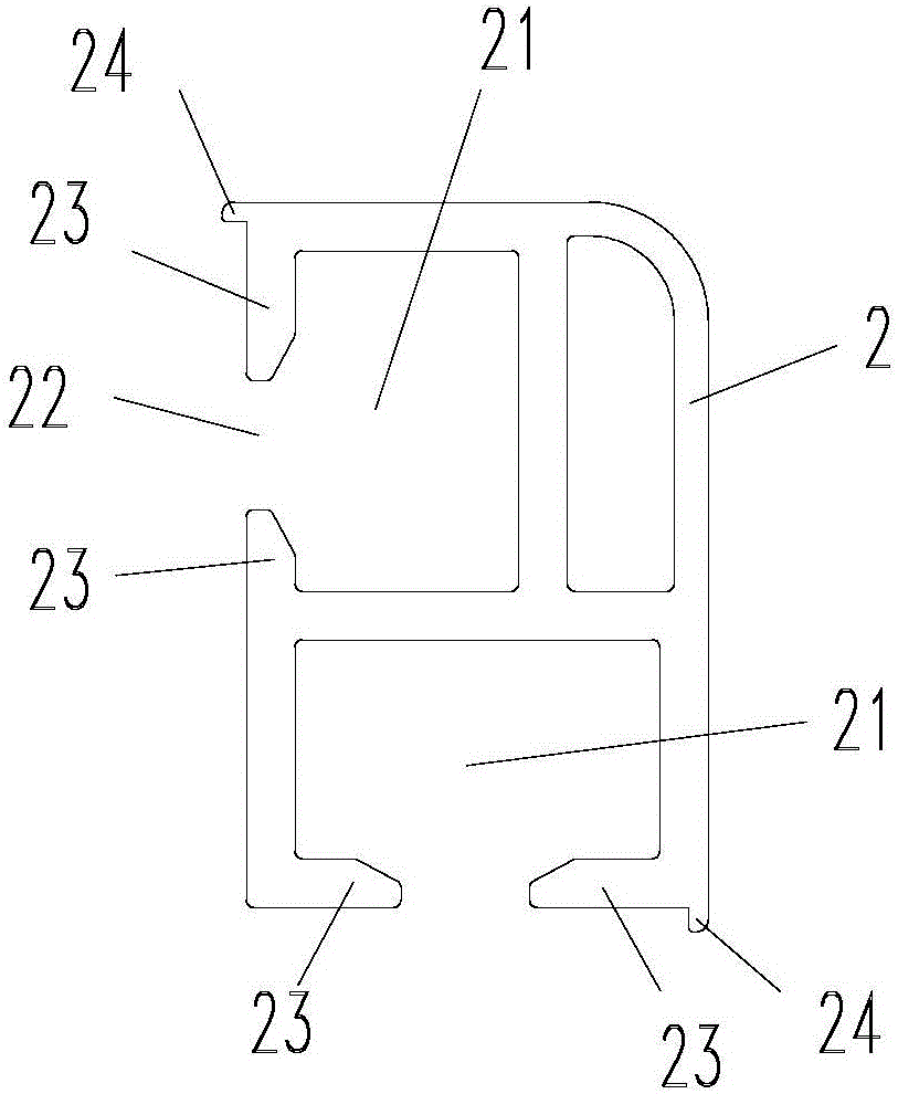
[0038] In this embodiment, the board connection structure is described by taking the connection of two boards as an example. The structure is as follows Figure 1 ~ Figure 4 As shown; including a cylinder 2, a connecting rod 3 and two plates 1; two sides in the cylinder 2 are respectively provided with positioning grooves 21 along the length direction; each positioning groove notch 22 sides are respectively provided with positioning edges twenty three.

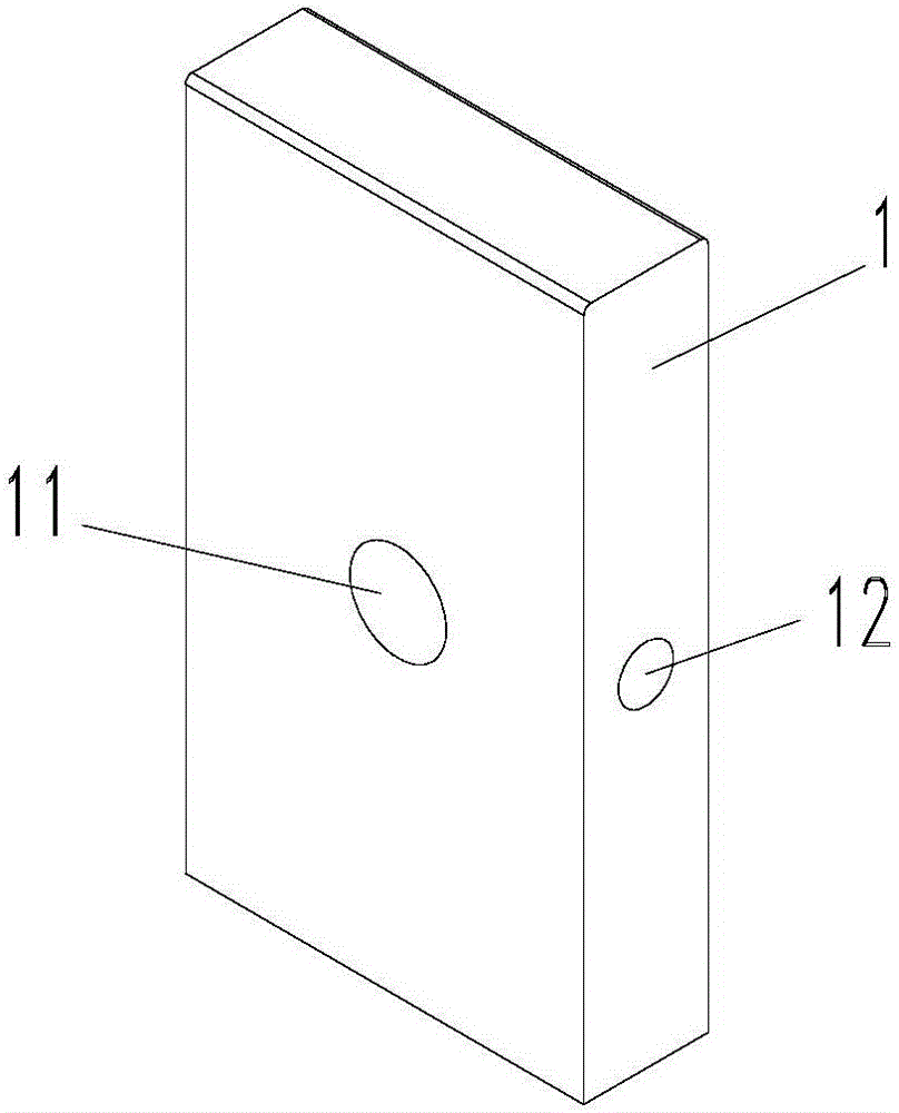
[0039]Each plate 1 is provided with accommodating cavity 11 respectively; the cavity wall of accommodating cavity 11 is provided with positioning hole 12; accommodating cavity 11 is provided with connecting auxiliary parts; in this embodiment, connecting auxiliary parts adopt eccentric wheel 4; accommodating cavity 11 and eccentric The wheel 4 matches; the eccentric wheel 4 can adopt the eccentric wheel in the existing three-in-one connector. One end of the connecting rod 3 is arranged in the positioning groove 21 and fits wi...

Embodiment 2

[0046] The plate connection structure of this embodiment, its structure is as follows Figure 5 and Figure 6 Shown; The difference with Embodiment 1 is: In this embodiment, the upper end and / or lower end of the cylinder 2 is provided with a cover body 5 . The cover body 5 includes a base plate 51 and at least one protrusion 52 clamped in the positioning groove 21 ; the protrusion 52 is connected with the base plate 51 . The advantage of this design is that the structure is simple, and it is convenient to cover the cover body 5 on the column body 2 . The cover body 5 can prevent foreign matter such as dust from accumulating inside the cylinder body 2, which is convenient for cleaning, keeps the product clean, and can also enhance the aesthetic feeling. The rest of the structure of this embodiment is the same as that of Embodiment 1.

Embodiment 3

[0048] The difference between the plate connection structure of this embodiment and Embodiment 1 is that: in this embodiment, the connecting rod includes a connecting rod body and a positioning piece sleeved on the connecting rod body; one end of the connecting rod body is offset against the positioning edge through the positioning piece , the other end of the connecting rod body passes through the positioning hole and is engaged with the eccentric wheel. The positioning piece and the main body of the connecting rod are set independently, and the positioning piece can be made of a material with certain elasticity, such as plastic, silica gel, etc., which is conducive to further strengthening the stability of the connection between the connecting rod and the column.

[0049] One end of the connecting rod body is provided with a limiting part, the limiting part fits with the positioning part, and the positioning part fits with the positioning edge, so that when the eccentric whee...


PUM


Abstract

The invention provides a plate connecting structure. The plate connecting structure is characterized by comprising a column, a connecting rod and at least two plates; positioning grooves are formed in at least two side faces of the column in the length direction; positioning edges are arranged on the two sides of a notch of each positioning groove; one end of the connecting rod abuts against the interiors of the positioning grooves, and therefore the connecting rod and the column can be fixed; the other end of the connecting rod extends out of the positioning grooves, and the other end of the connecting rod and the plates are fixed through connecting auxiliary pieces; and the plates are attached to the column. According to the plate connecting structure, position deviation between the plates due to trepanning position deviation can be avoided, the pass percent of products is increased, and the quality of the products is improved. The invention further provides a plate connecting method capable of achieving position alignment between the plates, easy and convenient to operate and capable of improving the assembly efficiency and lowering the technology difficulty.

Description

technical field [0001] The present invention relates to the technical field of panel connection, and more specifically, to a panel connection structure and a panel connection method. Background technique [0002] In the furniture manufacturing industry, boards are often used to splice into cabinets, tables and other furniture. Connections between existing adjacent boards are usually connected by connecting pieces, such as screws, three-in-one connecting pieces, and the like. However, the use of these connectors requires opening holes on the adjacent boards, and then the connectors are installed in the holes to realize the connection. However, these connection methods have high requirements on the hole processing, and the hole position cannot be deviated, otherwise there will be deviations after the plates are connected, resulting in problems such as unevenness of adjacent plates or gaps between adjacent plates, which will affect Product quality and aesthetics may even lead...

Claims


Application Information

Patent Timeline
Patent Type & Authority Applications(China)
IPC IPC(8): F16B5/00
CPCF16B5/0008F16B5/008
Inventor 付建平
Owner 佛山维尚家具制造有限公司
Why Eureka
Try Eureka