Device and method for detecting carbon fiber composite material truss bonding defects by ultrasonic phased array

A technology of ultrasonic phased array and composite materials, which is applied in the directions of measuring devices, analyzing materials, and analyzing solids by using sound waves/ultrasonic waves/infrasonic waves, etc. It can solve the problems that the efficiency cannot meet the progress of satellite verification, the payload cabin is bulky and difficult to realize, etc. , to achieve intuitive defect display, improve detection efficiency, and accurate measurement results

Inactive Publication Date: 2016-08-31
SHANGHAI INST OF SATELLITE EQUIP
View PDF5 Cites 25 Cited by
  • Summary
  • Abstract
  • Description
  • Claims
  • Application Information

AI Technical Summary

Problems solved by technology

However, the payload compartment of a satellite is usually assembled from dozens of rods and joints of different specifications and shapes. A single joint connects 3 to 10 carbon fiber composite rods to form a complex spatial structure. Usually located at the position where the rod is connected to the joint, the detection mechanism cannot be reached, so the ultrasonic C-scan detection method is difficult to implement on the detected object
With the increase of the satellite platform, the volume of the payload compartment is also getting larger and larger, and the efficiency of conventional ultrasonic testing methods cannot meet the needs of satellite verification progress

Method used


Image

  • Device and method for detecting carbon fiber composite material truss bonding defects by ultrasonic phased array
  • Device and method for detecting carbon fiber composite material truss bonding defects by ultrasonic phased array
  • Device and method for detecting carbon fiber composite material truss bonding defects by ultrasonic phased array

Examples


Embodiment Construction

[0036] The following will combine Figure 1 to Figure 5 The ultrasonic phased array detection device and method for carbon fiber composite material truss bonding defects of the present invention will be further described in detail.

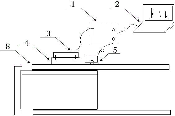
[0037] image 3 Shown is a schematic diagram of an ultrasonic phased array detection device for carbon fiber composite material truss bonding defects according to a preferred embodiment of the present invention. like image 3 As shown, the ultrasonic phased array detection device for carbon fiber composite truss bonding defects includes an ultrasonic phased array detector 1, a control computer 2, an ultrasonic phased array probe 3, a coupling wedge 4, a displacement encoder 5, and a coupling agent and comparison test block;

[0038] The ultrasonic echo signal output end of the ultrasonic phased array detector 1 is connected to the signal input end of the control computer 2 through a USB interface, and the control computer 2 is loaded with detec...


PUM

PropertyMeasurementUnit
diameteraaaaaaaaaa

Abstract

The invention relates to a device and a method for detecting carbon fiber composite material truss bonding defects by an ultrasonic phased array. The device comprises an ultrasonic phased array detector, a control computer, an ultrasonic phased array probe, a coupling wedge block, a displacement encoder, a coupling agent and a comparison specimen, wherein the ultrasonic phased array detector is connected with the control computer; the ultrasonic phased array probe is connected with the ultrasonic phased array detector; the probe end of the ultrasonic phased array probe is fixedly arranged on the coupling wedge block; the displacement encoder is connected with the ultrasonic phased array detector; the displacement encoder is fixedly connected with the coupling wedge block. The detection method comprises the following steps of connecting the detection device; setting the detection parameters; calibrating the ultrasonic phased array detector; adjusting scanning sensitivity; implementing detection; obtaining and recording the detection data. The device and the method have the advantages that the carbon fiber composite material truss bonding part with complicated space structure is detected, the better flexibility in use is realized, and the detection efficiency and the visual degree of detection results are improved.

Description

[0001] technical field [0002] The invention relates to the field of non-destructive testing, in particular to an ultrasonic phased array testing device and method for carbon fiber composite material truss bonding defects. [0003] Background technique [0004] Carbon fiber composites are widely used in the aerospace field due to their excellent structural properties and performance. The manufacture of the truss structure of the payload compartment of the new model satellite is made of rods and joints made of carbon fiber composite materials of different specifications through gluing. The quality of the bonding quality affects the stability and accuracy of the entire truss structure. Therefore, it is necessary to determine whether the bonding quality meets the technical requirements through non-destructive testing methods. figure 1 A schematic diagram of the satellite payload bay truss structure is shown, figure 2 Shown is a schematic diagram of the structure of ...

Claims


Application Information

Patent Timeline
Patent Type & Authority Applications(China)
IPC IPC(8): G01N29/06G01N29/04
CPCG01N29/069G01N29/048
Inventor 邵红亮曹勇孙建罡
Owner SHANGHAI INST OF SATELLITE EQUIP
Why Eureka
Try Eureka