Experimental device and method for measuring Young's modulus of metallic wire by using resonant principles

A technology of Young's modulus and experimental device, which is used in teaching models, educational appliances, and analysis of solids using sonic/ultrasonic/infrasonic waves, etc., can solve the problems of wrong data, difficult adjustment of telescopes, and single principle, and achieves enhanced solutions. The ability to ask questions, cultivate the spirit of innovation, and enrich the effect of experimental content

Inactive Publication Date: 2016-08-31
田凯
View PDF0 Cites 0 Cited by
  • Summary
  • Abstract
  • Description
  • Claims
  • Application Information

AI Technical Summary

Problems solved by technology

[0005] First, the Young's modulus of metal wire is usually measured by static stretching method, and the principle is relatively simple
[0006] Second, according to the optical lever amplification principle to measure the tiny elongation of the metal wire, the adjustment of the telescope is relatively difficult, and there are many precautions, and it is very easy to get tired and make mistakes in the data when observing and measuring directly with the telescope through the human eye. , affecting the accuracy of the measurement results

Method used


Image

  • Experimental device and method for measuring Young's modulus of metallic wire by using resonant principles
  • Experimental device and method for measuring Young's modulus of metallic wire by using resonant principles
  • Experimental device and method for measuring Young's modulus of metallic wire by using resonant principles

Examples


Embodiment Construction

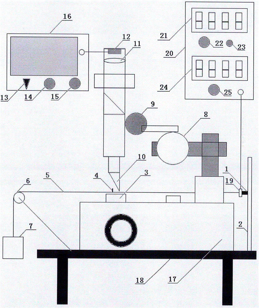
[0037] Among the figure, a vertical support 2 is set at one end of the test bench 18, and an inclined support 6 with a pulley on the top is set at the other end. A chuck 1 and a vibrator 19 are arranged on the vertical support 2. The chuck 1 can be The vertical support 2 moves to change the position. One end of the metal wire 5 is connected with the chuck 1 and the vibrator 19, and the other end is connected to the iron block 7 across the pulley on the inclined support 6 with a pulley on the top. A positioning marker point 4 . The exciter 19 is connected to the sinusoidal signal source 20 through the interface, and the sinusoidal signal voltage amplitude output by the sinusoidal signal source 20 can be continuously adjusted by the sinusoidal signal voltage amplitude adjustment knob 25, and can be displayed on the sinusoidal signal voltage amplitude display screen 24; The frequency of the sinusoidal signal can be continuously adjusted through the coarse sinusoidal signal freque...


PUM


Abstract

The invention provides an experimental device and method for measuring Young's modulus of a metallic wire by using resonant principles and relates to devices and methods for measuring the Young's modulus. The device and the method are used for solving the problems in experiments of college physics at present that the experimental principle for measuring the Young's modulus of the metallic wire is single and abstract, and the difficulty of adjustment on a telescope is high. The device provided by the invention comprises a vertical bracket and an inclined bracket which are arranged at the two ends of an experimental table, wherein a collet and a vibration exciter are arranged on the vertical bracket, the two ends of the metallic wire which is provided with locating identification points are separately connected with the vibration exciter and an iron block, the vibration exciter is connected with a signal source, and a CCD (Charge Coupled Device) sensor is arranged in front of a reading microscope eyepiece. The method provided by the invention comprises the steps of converting sinusoidal signals into mechanical vibrations by using the vibration exciter, enabling a metallic wire spring vibrator to be subjected to forced vibration, observing conditions of vibration of images of the locating identification points on a display, adjusting signal frequency, obtaining natural frequency of the metallic wire spring vibrator when the amplitude of vibration is the highest, and substituting the natural frequency into an equation, so as to figure out the Young's modulus of the metallic wire. The device and the method are applicable to the measurement on the Young's modulus of the metallic wire.

Description

technical field [0001] The invention relates to a university physics experiment device, in particular to an experiment device and method for measuring the Young's modulus of a metal wire by using the resonance principle. Background technique [0002] The change in shape of a solid under the action of an external force is called deformation. It can be divided into elastic deformation and normative deformation. The deformation that an object can completely return to its original shape after the external force is removed is called elastic deformation. If the external force applied to the object is too large, so that after the external force is removed, the object cannot completely return to its original shape, leaving residual deformation, which is called normative deformation. In this experiment, only elastic deformation is studied. Therefore, the magnitude of the external force should be controlled to ensure that the object can return to its original shape after the extern...

Claims


Application Information

Patent Timeline
Patent Type & Authority Applications(China)
IPC IPC(8): G01N29/12G09B23/10
CPCG01N29/12G09B23/10
Inventor 田凯王志刚王丽霞王鸿运赵鹏涛
Owner 田凯
Why Eureka
Try Eureka