Experiment device and method utilizing resonance principle to measure Young modulus of metal wire

A technology of Young's modulus and experimental device, applied in teaching models, educational appliances, and analysis of solids using sonic/ultrasonic/infrasonic waves, etc., can solve the problems of wrong data, single principle, and difficult adjustment of telescopes

Inactive Publication Date: 2016-10-26
田凯
View PDF0 Cites 0 Cited by
  • Summary
  • Abstract
  • Description
  • Claims
  • Application Information

AI Technical Summary

Problems solved by technology

[0005] First, the Young’s modulus of metal wire is usually measured by static stretching method, the principle is relatively simple
[0006] Second, according to the optical lever amplification principle, the tiny elongation of the metal wire is measured through the amplification system composed of optical levers, telescopes and rulers. Although the method is ingenious, the principle is abstract and difficult to understand. The adjustment of the telescope is relatively difficult. Notes There are many, and it is very easy to get tired and make mistakes in the data, which will affect the accuracy of the measurement results.
[0007] Third, weights are generally used to apply tension to the wire, and the nominal mass of the weights is used to calculate the tension inaccurately, thus affecting the accuracy of the experimental results

Method used


Image

  • Experiment device and method utilizing resonance principle to measure Young modulus of metal wire
  • Experiment device and method utilizing resonance principle to measure Young modulus of metal wire
  • Experiment device and method utilizing resonance principle to measure Young modulus of metal wire

Examples


Embodiment Construction

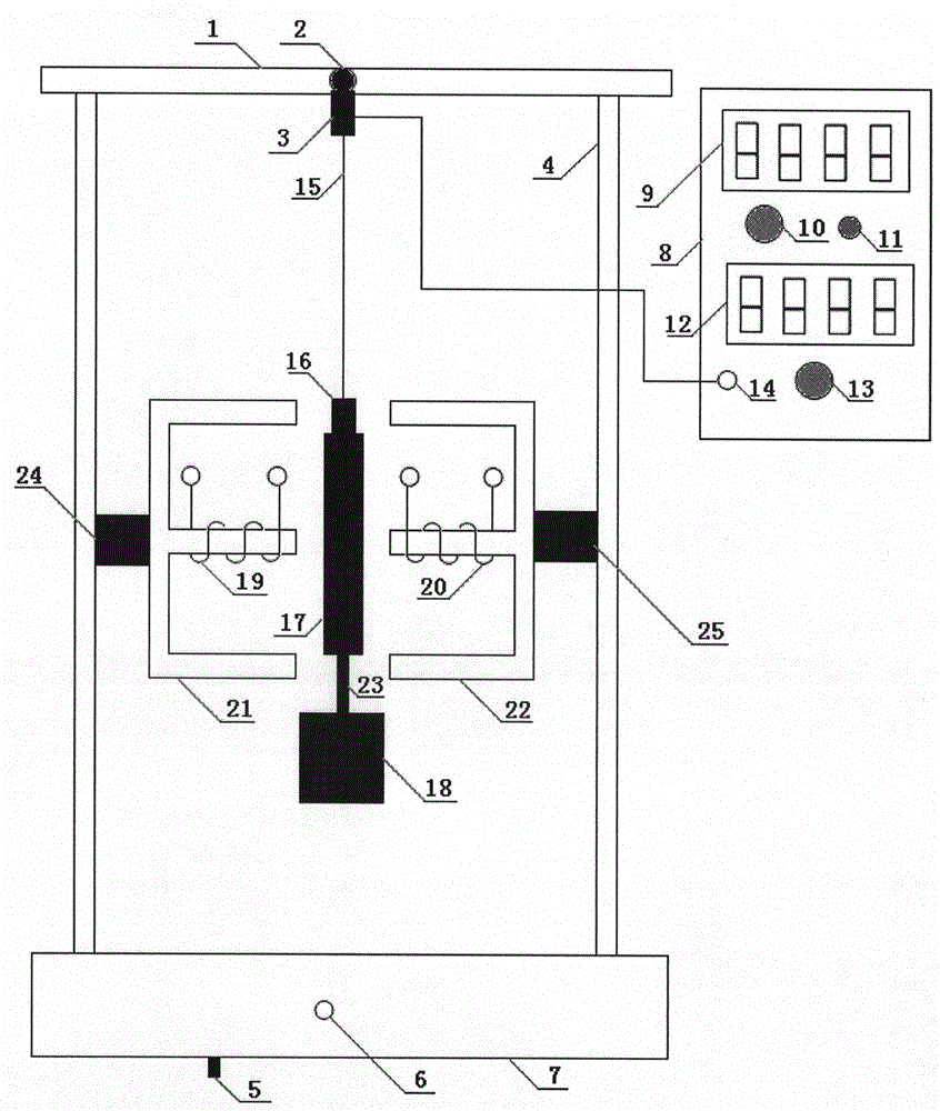
[0039] In the figure, a bracket 4 is set on the bracket base 7, a beam 1 is set on the upper end of the bracket 4, an upper chuck 2 and a vibrator 3 are arranged in the middle of the beam 1, and one end of a metal wire 15 is connected with the upper chuck 2 and the vibration exciter 3, and the other One end is connected with the lower chuck 16, and the lower chuck 16 is fixed with a movable armature 17, and the movable armature 17 is connected with an iron block 18 through a connecting device 23. The exciter 3 is connected to the sinusoidal signal source 8 through the interface 14 between the exciter and the sinusoidal signal source, and the sinusoidal signal voltage amplitude output by the sinusoidal signal source 8 can be continuously adjusted by the sinusoidal signal voltage amplitude adjustment knob 13, and can be adjusted at The sinusoidal signal voltage amplitude is displayed on the display screen 12; the sinusoidal signal frequency can be continuously adjusted through th...


PUM


Abstract

The invention discloses an experiment device and method utilizing a resonance principle to measure the Young modulus of a metal wire, relates to a Young modulus measuring device and method, and aims to solve the problems that in the conventional university physical experiments, the experiment principle for measuring metal wire Young modulus is single and abstract, and the telescope is hard to adjust. The provided device comprises a crossbeam, which is arranged on the upper end of a support. An upper clamping head and a vibration generator are arranged on the middle of the crossbeam. Two ends of a metal wire are respectively connected to the vibration generator and a movable armature. The vibration generator is connected to a signal source. A measuring device is composed of a differential bridge composed of an inductance coil and an adjustable resistance, an alternating voltage source, an amplifying device, and an oscilloscope. According to the method, sinusoidal signals are converted into mechanical vibration by the vibration generator to force a metal wire spring oscillator to vibrate; the electric bridge composed of variable inductances is converted into electric signals, the signal frequency is adjusted, when the waveform amplitude is the largest, the inherent frequency of the metal wire spring oscillator can be obtained, and finally the inherent frequency is substituted into a formula to calculate the Young modulus of the metal wire. The provided method is suitable for measuring the Young modulus of a metal wire.

Description

technical field [0001] The invention relates to a university physics experiment device, in particular to an experiment device and method for measuring the Young's modulus of a metal wire by using the resonance principle. Background technique [0002] The change in shape of a solid under the action of an external force is called deformation. It can be divided into elastic deformation and normative deformation. The deformation that an object can completely return to its original shape after the external force is removed is called elastic deformation. If the external force applied to the object is too large, so that after the external force is removed, the object cannot completely return to its original shape, leaving residual deformation, which is called normative deformation. In this experiment, only elastic deformation is studied. Therefore, the magnitude of the external force should be controlled to ensure that the object can return to its original shape after the extern...

Claims


Application Information

Patent Timeline
IPC IPC(8): G01N29/12G09B23/10
CPCG01N29/12G01N2291/014G01N2291/0234G01N2291/02827G09B23/10
Inventor 田凯蔡晓艳王宁赵鹏涛胡彬
Owner 田凯
Why Eureka
Try Eureka