Liquid crystal display driving method, liquid crystal display and display device

A technology of a liquid crystal display and a driving method, applied in the field of liquid crystal displays and display devices, capable of solving problems such as insufficient charging rate of pixels of a liquid crystal display, and achieving the effect of ensuring picture quality and improving charging rate

Inactive Publication Date: 2016-08-31
BOE TECH GRP CO LTD
View PDF9 Cites 20 Cited by
  • Summary
  • Abstract
  • Description
  • Claims
  • Application Information

AI Technical Summary

Problems solved by technology

[0005] A method for driving a liquid crystal display, a liquid crystal display and a display device provided in an embodiment of ...

Method used


Image

  • Liquid crystal display driving method, liquid crystal display and display device
  • Liquid crystal display driving method, liquid crystal display and display device
  • Liquid crystal display driving method, liquid crystal display and display device

Examples


Embodiment 1

[0050] Since the corresponding initial driving voltage is applied to each pixel when the liquid crystal display is displaying each frame, the compensation voltage may be related to the initial driving voltage applied to each pixel.

[0051] During specific implementation, in the above driving method provided by the embodiment of the present invention, for each frame of image data, the larger the voltage range of the initial driving voltage corresponding to each pixel, the larger the voltage range of the compensation voltage corresponding to each pixel.

Embodiment 2

[0053] When the liquid crystal display displays a frame, what is applied to each pixel is the initial driving voltage of the current frame, and the initial driving voltage applied to each pixel is not changed until the next frame is displayed, so the compensation voltage can be compared with It is related to the voltage difference between the initial driving voltages of the same pixel when displaying two adjacent frames of pictures.

[0054] In specific implementation, in the above driving method provided by the embodiment of the present invention, for each frame of image data except the first frame of image data, the initial driving voltage corresponding to each pixel and the initial driving voltage of the previous frame of image data The greater the voltage difference between the pixels, the greater the voltage range of the compensation voltage corresponding to each pixel.

[0055] In a specific implementation, in order to improve the overall image quality, when displaying t...

Embodiment 3

[0059] During specific implementation, in the above-mentioned driving method provided by the embodiment of the present invention, for each frame of image data, the voltage amplitude of the compensation voltage corresponding to each pixel is a fixed value.

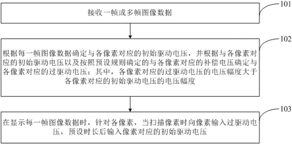
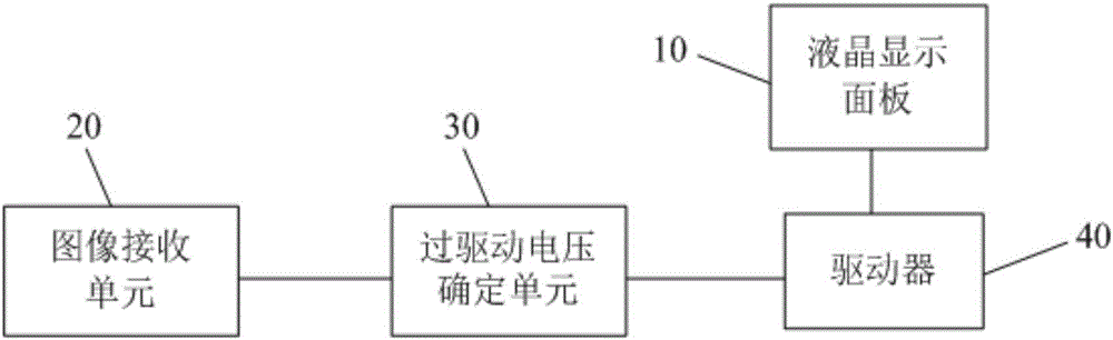
[0060] Based on the same inventive concept, an embodiment of the present invention also provides a liquid crystal display, a liquid crystal display panel 10 with a plurality of pixels, such as image 3 As shown, it also includes: an image receiving unit 20, configured to receive one or more frames of image data;

[0061] An overdrive voltage determining unit 30, configured to determine an initial drive voltage corresponding to each pixel according to each frame of image data, and determine an initial drive voltage corresponding to each pixel and a compensation voltage corresponding to each pixel determined according to a preset rule. An overdrive voltage corresponding to each pixel; wherein, the voltage amplitude of the ove...


PUM


Abstract

The invention discloses a liquid crystal display driving method, a liquid crystal display and a display device. In display of image data of each frame, overdrive voltage with voltage amplitude greater than preset duration of the voltage amplitude of an initial driving voltage is firstly applied to each pixel so that liquid crystal molecules approach to a target deflecting angle, and then corresponding initial driving voltage is applied to each pixel so that the liquid crystal molecules quickly reach the target deflecting angle to improve the charging rate of the pixel, thus ensuring the picture quality of the liquid crystal display.

Description

technical field [0001] The invention relates to the field of display technology, in particular to a driving method of a liquid crystal display, a liquid crystal display and a display device. Background technique [0002] A liquid crystal display generally includes an upper substrate and a lower substrate of a cell, and a layer of liquid crystal molecules filled between the upper substrate and the lower substrate. When displaying a picture, due to the formation of an electric field between the driving voltage loaded on the pixel electrode of each pixel and the common electrode voltage on the common electrode, the liquid crystal molecules will deflect under the action of the electric field, and the degree of deflection is different, resulting in different transmittance. , so as to realize the screen display. [0003] However, since the liquid crystal molecules have a viscous effect, there will be a time course for the liquid crystal molecules to deflect to the expected state,...

Claims


Application Information

Patent Timeline
IPC IPC(8): G09G3/36
CPCG09G3/3688G09G3/3696G09G3/3685G09G2320/0252H04N25/709G09G3/34
Inventor 韩承佑商广良
Owner BOE TECH GRP CO LTD
Why Eureka
Try Eureka