Antenna rotation mechanism and antenna

A technology for rotating mechanisms and antennas, applied to antennas, electrical components, etc., can solve the problems of easily affected antenna intermodulation and unstable single-point rotation, and achieve the effects of maximizing space utilization, avoiding overturning damage, and flexible implementation methods

Active Publication Date: 2016-08-31
COMBA TELECOM TECH (GUANGZHOU) CO LTD
View PDF5 Cites 3 Cited by
  • Summary
  • Abstract
  • Description
  • Claims
  • Application Information

AI Technical Summary

Problems solved by technology

[0004] The primary purpose of the present invention is to provide an antenna rotation mechanism to solve the problem of single-point rotation instability, and to further solve the problem that antenna intermodulation is easily affected

Method used


Image

  • Antenna rotation mechanism and antenna
  • Antenna rotation mechanism and antenna
  • Antenna rotation mechanism and antenna

Examples


Embodiment Construction

[0036] Embodiments of the present invention are described in detail below, examples of which are shown in the drawings, wherein the same or similar reference numerals designate the same or similar elements or elements having the same or similar functions throughout. The embodiments described below by referring to the figures are exemplary only for explaining the present invention and should not be construed as limiting the present invention.

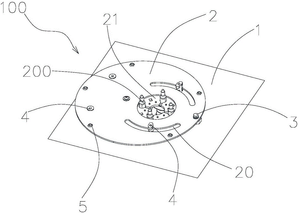
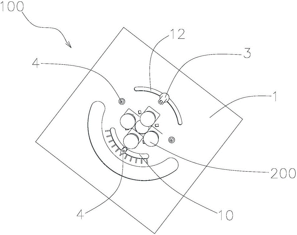
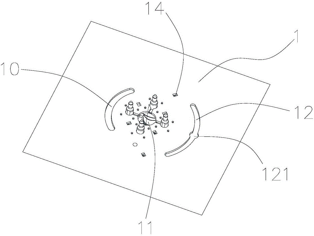
[0037] Such as Figure 1 to Figure 9 As shown, the present invention relates to an antenna rotation mechanism 100, which is used to connect with the antenna main body (not shown in the figure, the same below) to adjust the horizontal angle of the antenna. The antenna referred to here is, for example, a sector antenna suitable for outdoor use.

[0038] The antenna rotation mechanism 100 includes a base plate 1 , a rotating disk 2 rotatably disposed above the base plate 1 for fixing the antenna body, and a limiting component 4 connected t...


PUM


Abstract

The invention provides an antenna rotation mechanism. The mechanism comprises a substrate and a rotating disc which is used for fixing an antenna main body and can be rotatably arranged on the substrate. The substrate and/or the rotating disc is provided with at least one arc limiting groove. Projections of centers of circles of the plurality of arc limiting grooves on the substrate are mutually superposed. A limiting assembly which is connected to the substrate and the rotating disc is arranged in each arc limiting groove. Through the plurality of concentric arc limiting grooves and the limiting assembly, a rotation angle of the rotating disc is limited and a virtual rotating shaft is constructed. An entity rotating shaft does not need to be installed so that occupation of the rotating shaft to a substrate installation space is avoided. In addition, the invention also relates to an antenna adopting the antenna rotation mechanism. The antenna possesses characteristics that the size is small; the structure is firm and reliable; and cross modulation is stable.

Description

technical field [0001] The present invention relates to the technical field of mobile communication, in particular, the present invention relates to an antenna rotating mechanism and an antenna. Background technique [0002] With the in-depth development of the mobile communication industry, operators put forward higher and higher requirements for network optimization in their network construction. [0003] Currently on the market, the internal horizontal rotation mechanism of the electronically adjustable antenna generally rotates around a single axis, which has disadvantages such as unstable single-point rotation, affecting antenna intermodulation, difficult design, and occupying rotation space. With the development of products, its integration level is getting higher and higher, and the antenna is getting smaller and smaller, and the space for installing the horizontal rotation mechanism inside the antenna is becoming more and more limited. The mechanism can be applied t...

Claims


Application Information

Patent Timeline
Patent Type & Authority Applications(China)
IPC IPC(8): H01Q3/02H01Q3/06
CPCH01Q3/02H01Q3/06
Inventor 黄潮生游建军胡成才黄明达刘聪
Owner COMBA TELECOM TECH (GUANGZHOU) CO LTD
Why Eureka
Try Eureka