Dental handpiece driller clamping device

A dental handpiece and clamping device technology, which is applied in dentistry, dental drilling, medical science, etc., can solve the problems of not clamping the needle tightly, affecting the user experience, and laborious needle replacement, etc., to achieve increased speed and large clamping force , long service life effect

Active Publication Date: 2016-09-07
GUILIN WOODPECKER MEDICAL INSTR
View PDF8 Cites 2 Cited by
  • Summary
  • Abstract
  • Description
  • Claims
  • Application Information

AI Technical Summary

Problems solved by technology

The clamping force of this kind of shaft core is very large, and the service life is also very long, but this kind of shaft core also has the problem that the pressing part does not rebound and the bur

Method used


Image

  • Dental handpiece driller clamping device
  • Dental handpiece driller clamping device
  • Dental handpiece driller clamping device

Examples


Embodiment 1

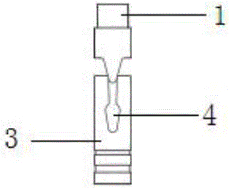
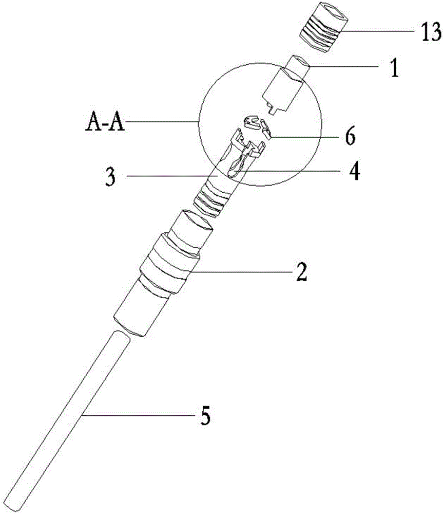
[0031] Such as figure 2 As shown, a dental handpiece bur clamping device includes a pressing member 1 and a bushing 2, the pressing member 1 can slide up and down at the top of the bushing 2, and the upper end of the pressing member 1 extends Out of the top of the shaft sleeve 2 , between the pressing member 1 and the needle clamping member 3 is provided a guide sleeve 13 for guiding the pressing member 1 to slide up and down. A needle holder 3 is provided inside the bushing 2 and corresponding to the position below the pressing member 1, and the side wall of the top of the needle holder 3 is provided with two vertically arranged gaps that can be opened under pressure. 4. Pressing down on the pressing part 1 can squeeze the top of the needle clamping part 3 so that the notch 4 opens and clamps the bur 5 in the needle clamping part 3, and the inside of the bushing 2 corresponds to the pressing An elastic piece is provided between the piece 1 and the needle clamping piece 3 to...

Embodiment 2

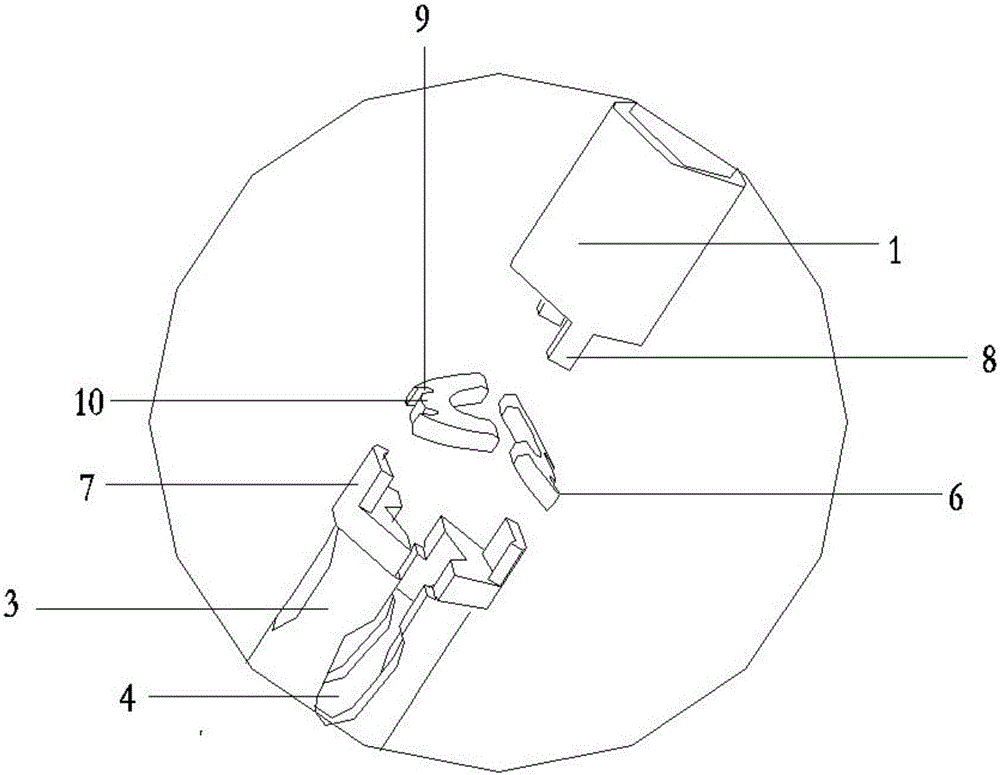
[0035] Figure 4 It is a schematic diagram of the second embodiment of the elastic member, and the structural principle of the other parts of the clamping device is the same as that of the first embodiment except the elastic member. The elastic member is two V-shaped elastic pieces 6 arranged symmetrically with respect to the axis of the pressing member 1. A vertically upward extrusion block 11 is provided at the opening of the V-shaped elastic piece 6. The top of the needle clip 3 The outer periphery is provided with a baffle plate 7 that extends upward and is oppositely arranged. The closed ends of the V-shaped elastic pieces 6 are against the baffle plate 7 respectively, and the top of the extrusion block 11 of the V-shaped elastic piece 6 is against the top of the pressing piece 1. bottom, and the V-shaped shrapnel 6 is arranged obliquely upward in the direction from its closed end to its open end. The clamping device using the above-mentioned elastic member also inherits...

Embodiment 3

[0037] Figure 5 It is a schematic diagram of the third embodiment of the elastic member. The structural principle of the other parts of the clamping device except the elastic member is also the same as that of Embodiment 1. The elastic member is curved upwards, and the needle clamping member 3 An upwardly extending and opposite baffle plate 7 is provided on the outer periphery of the top, the two ends of the elastic member are against the baffle plate 7 respectively, and the highest point of the elastic member is against the bottom of the pressing member 1 . The elastic member is provided with a through hole 12 for the elastic member to be easily deformed under force. The clamping device using the above-mentioned elastic member can also achieve the beneficial effects of the above-mentioned embodiment.


PUM


Abstract

The invention relates to a dental handpiece driller clamping device, which comprises a pressing element and a shaft sleeve, wherein the pressing element is positioned at the top inside the shaft sleeve in a way capable of vertically sliding; the upper end of the pressing element extends out of the top of the shaft sleeve; a driller clamping element is arranged in a position, corresponding to the lower side position of the pressing element, in the shaft sleeve; two notches which are in vertical arrangement and can be opened when being pressed are oppositely formed in the side wall of the top of the driller clamping element; the top of the driller clamping element can be extruded by downwards pressing the pressing element, so that the notches can be opened to tightly clamp a driller arranged in the driller clamping element; and an elastic element used for upwards rebounding the downwards pressed pressing element is arranged in a position, corresponding to the position between the pressing element and the driller clamping element, in the shaft sleeve. The dental handpiece driller clamping device has the beneficial effects that the clamping device inherits the advantages of a KV shaft core; meanwhile, the elastic element for upwards rebounding the pressing element is added; the driller can be released by the driller clamping element by downwards pressing the pressing element again; the driller change speed is accelerated; the corresponding pressing force is smaller than that in the prior art; and the user experience enhancement is facilitated.

Description

technical field [0001] The invention relates to the field of medical instruments, in particular to a dental handpiece bur clamping device. Background technique [0002] The dental handpiece drives the wind wheel on the movement through compressed air, or through mechanical transmission such as gears, and then drives the bur to run at high speed to cut teeth and remove carious tissues, or prepare porcelain teeth, and can also be used to polish dentures . [0003] The push-type dental handpiece is the mainstream direction of dental handpiece development because of its convenient and fast needle replacement. When the clamping device of the dental handpiece presses the shaft core, the core component of the push-type dental handpiece, its main function is to quickly clamp the bur when loading the needle, and quickly release the bur when unloading the needle. It is required to be safe and stable when the dental handpiece is working. Clamp the needle. [0004] Such as figure 1 ...

Claims


Application Information

Patent Timeline
IPC IPC(8): A61C1/14
CPCA61C1/144A61C1/145A61C2204/00
Inventor 王宏灿李维李钊林黄永朝邓庆坚
Owner GUILIN WOODPECKER MEDICAL INSTR
Why Eureka
Try Eureka