Heating plaster

A heating paste and heating layer technology, which is applied in the field of daily necessities, can solve the problems of inconvenient stretching and bending of joint parts, and the powder of the heating layer is easy to fall to the bottom, etc.

Inactive Publication Date: 2016-09-07
JINAN SHENGQUAN GROUP SHARE HLDG
View PDF13 Cites 4 Cited by
  • Summary
  • Abstract
  • Description
  • Claims
  • Application Information

AI Technical Summary

Problems solved by technology

However, this heating patch has relatively large limitations. When it is used in a large area, it will cause inconvenience if the heating patch is directly attached to the human body, such as inco

Method used


Image

  • Heating plaster
  • Heating plaster
  • Heating plaster

Examples


Embodiment 1

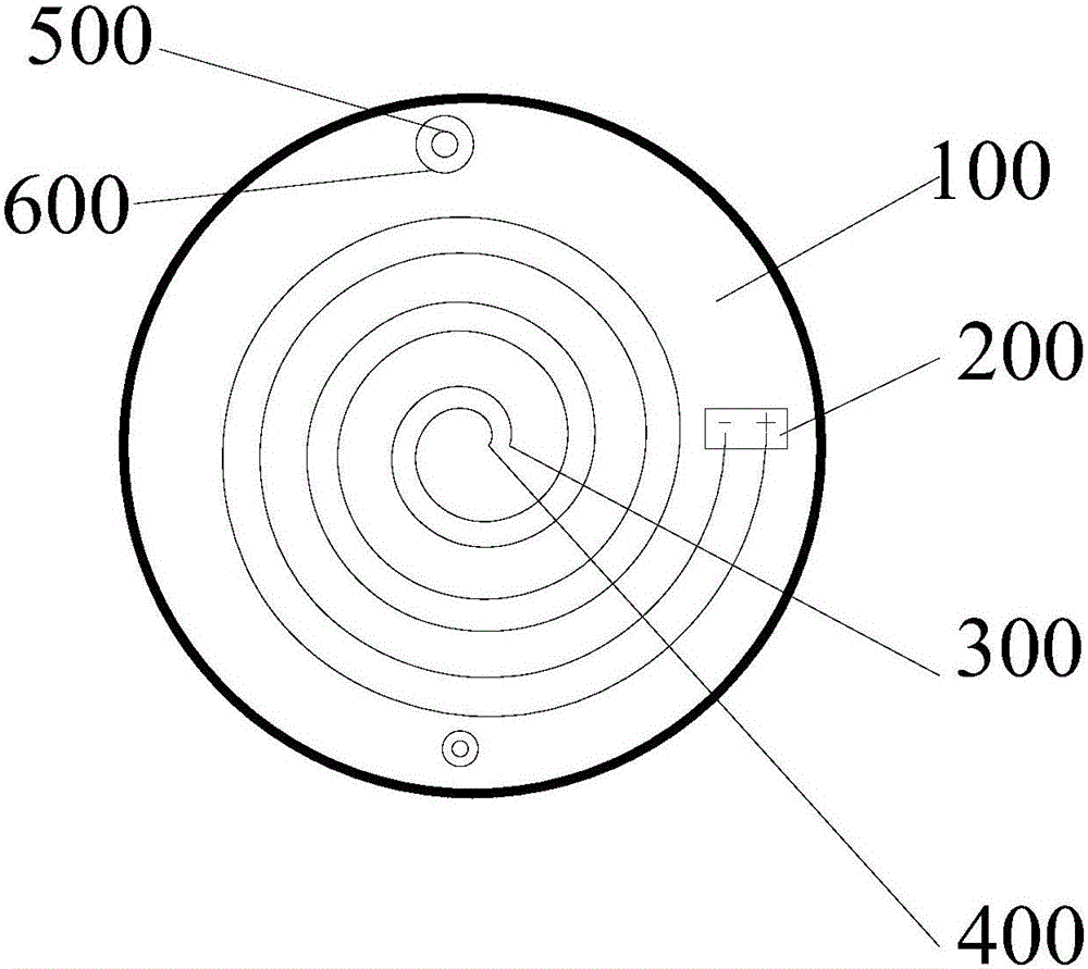
[0090] A heating paste, including a heating layer 7, a microcurrent layer 10, and an insulating protective layer 8; the microcurrent layer 10 includes a flexible conductive base layer 100 and a microcurrent power supply 200, and the insulating protective layer 8 is wrapped outside the heating layer 7, and is flexible and conductive The base is arranged on the wrapped heating layer 7, and the micro-current layer 10 is in direct contact with human skin.

[0091] The positive electrode of the micro-current power supply 200 is connected to the positive electrode conductive strip 300, and the negative electrode of the micro-current power supply 200 is connected to the negative electrode conductive strip 400; the positive electrode conductive strip 300 is arranged around the first set point in turn around the outer periphery of the first set point The negative electrode conductive strip 400 is arranged around the second set point in turn around the outer periphery of the second set p...

Embodiment 2

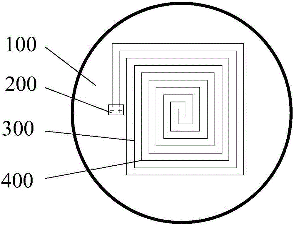
[0096] A kind of heating paste, comprises heating layer 7, micro current layer 10 and insulation protective layer 8; The current power source 202 and the insulating protection layer 8 are arranged between the flexible conductive base layer 100 and the heating layer 7, and the microcurrent layer 10 is in direct contact with human skin.

[0097] The positive pole of the first microcurrent power supply 201 connects the first positive pole conductive strip 301, and the negative pole of the first microcurrent power supply 201 connects the first negative pole conductive strip 401; The positive pole of the second microcurrent power supply 202 connects the second positive pole conductive strip 302, the second The negative electrode of the microcurrent power supply 202 is connected to the second negative electrode conductive strip 402 . The positive and negative conductive strips are distributed on the flexible conductive base layer 100 at positive and negative intervals, such as the f...

Embodiment 3

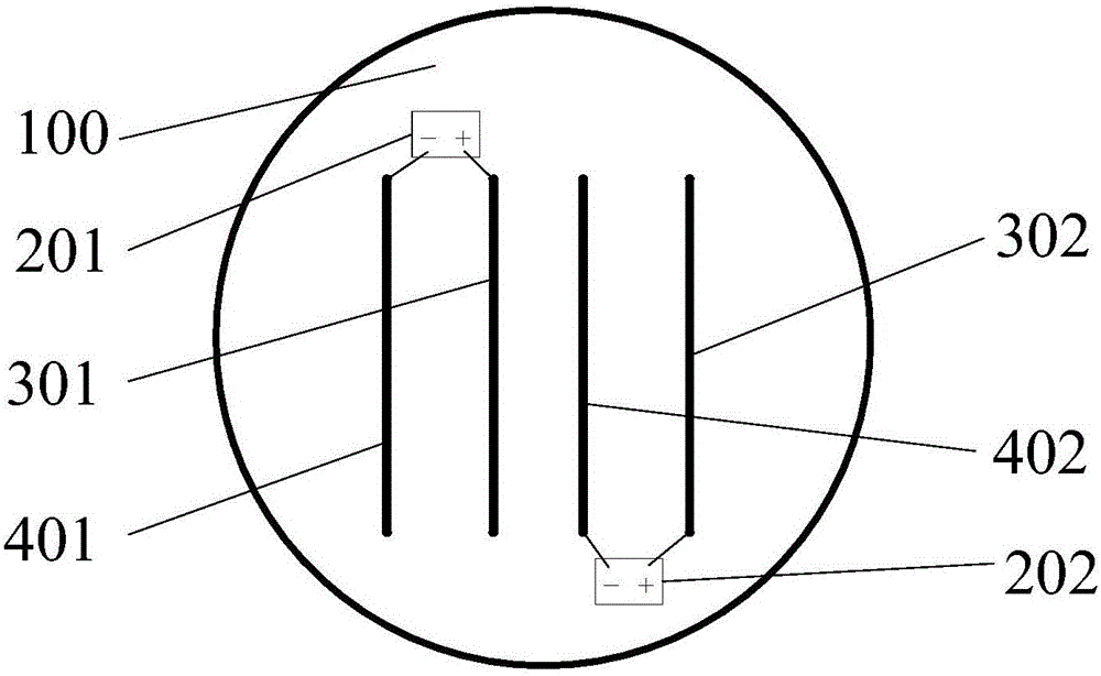
[0101] A kind of heating paste, comprises heating layer 7, micro current layer 10 and insulation protective layer 8; The current power source 202 and the insulating protection layer 8 are arranged between the flexible conductive base layer 100 and the heating layer 7, and the microcurrent layer 10 is in direct contact with human skin.

[0102] The positive pole of the first microcurrent power supply 201 connects the first positive pole conductive strip 301, and the negative pole of the first microcurrent power supply 201 connects the first negative pole conductive strip 401; The positive pole of the second microcurrent power supply 202 connects the second positive pole conductive strip 302, the second The negative electrode of the microcurrent power supply 202 is connected to the second negative electrode conductive strip 402 . The positive and negative intervals of the suspended ends of the conductive strips are arranged on the flexible conductive base layer 100, and the incl...


PUM


Abstract

The invention provides a heating plaster. The heating plaster comprises a heating layer and a microcurrent layer arranged on one side, close to the human body, of the heating layer, wherein the microcurrent layer comprises a flexible conductive base layer and at least one microcurrent power supply, and the flexible conductive base layer is arranged on the heating layer. The heating plaster can provide microcurrent and heat simultaneously, the heat can penetrate into the body easily under the effect of the microcurrent, and moreover, the heating time and heating amount of the heating plaster are adjustable; the microcurrent contacts the skin directly, thus the blood circulation of the skin can be promoted, and the effect of improving the skin state can be improved; in addition, the heating plaster is light in weight, and convenient to carry and use.

Description

technical field [0001] The invention belongs to the technical field of daily necessities, and relates to a heating patch, in particular to a heating patch with a micro-current power supply. Background technique [0002] The climate is cold in winter. In order to keep warm, people wear more clothes or use external heat sources such as stoves and hot water bottles to keep warm. However, wearing more clothes seems bloated and not beautiful enough. [0003] CN 202801900U discloses a new type of heating paste, comprising adhesive paper, adhesive layer, heating layer, breathable film, non-woven fabric, adhesive paper is bonded on the adhesive layer, and the heating layer is arranged on one side of the adhesive layer. The air-permeable film is arranged on one side of the heating layer, the non-woven fabric is arranged on one side of the air-permeable film, and the edge of the non-woven fabric is bonded to the edge of the adhesive layer. When using it, you only need to tear the out...

Claims


Application Information

Patent Timeline
IPC IPC(8): A61F7/02A61N1/18
CPCA61F7/02A61F7/007A61F2007/0088A61F2007/0226A61N1/18
Inventor 张金柱袁征刘顶张小鸽
Owner JINAN SHENGQUAN GROUP SHARE HLDG
Why Eureka
Try Eureka