Stamping device fixed firmly

A stamping device and solid technology, applied in the field of metal stamping, can solve the problems of damage to processed parts, waste of production costs, poor applicability, etc., and achieve the effects of improving production efficiency and cost, simple structure of the device, and convenient operation

Inactive Publication Date: 2016-09-07
CHANGZHOU RONGSHUN ELECTRONICS
View PDF8 Cites 0 Cited by
  • Summary
  • Abstract
  • Description
  • Claims
  • Application Information

AI Technical Summary

Problems solved by technology

[0002] Metal stamping is a manufacturing process that uses a metal stamping die or a series of metal stamping dies to form metal sheets into three-dimensional shape workpieces. Metal stamping products are used in various industries, such as: automobiles, household appliances, etc., automotive stamping parts It is an important part of the metal stamping industry. Metal stamping can form metal sheets very efficiently. Metal stamping dies are installed on a press, and each stroke of the press forms a workpiece. The production of metal stamping is done by metal stampers. Metal stamping Stamping dies are produced by machine tools or mold factories, and some machine tool and mold factories also produce stamping parts. However, when the stamping equipment on the market currently stamps, the stamped metal is not firmly fixed, and it is easy to cause the metal to fall off during stamping, resulting in processing The parts are damaged, the production cost is wasted, time-consuming and labor-intensive, and the applicability is poor

Method used


Image

  • Stamping device fixed firmly
  • Stamping device fixed firmly

Examples


Embodiment Construction

[0012] The following will clearly and completely describe the technical solutions in the embodiments of the present invention with reference to the accompanying drawings in the embodiments of the present invention. Obviously, the described embodiments are only some, not all, embodiments of the present invention. Based on the embodiments of the present invention, all other embodiments obtained by persons of ordinary skill in the art without making creative efforts belong to the protection scope of the present invention.

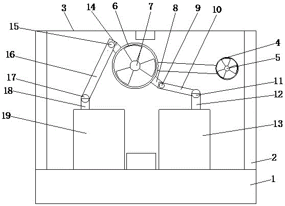
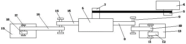
[0013] see Figure 1-2 , the present invention provides a technical solution: a fixed and firm stamping device, including a horizontal plate 3, brackets 2 are arranged on both sides of the bottom of the horizontal plate 3, the bottom of the bracket 2 is fixedly connected with the base 1, and the horizontal plate 3 is provided with There is a first turntable 4, the center of the first turntable 4 is provided with a first rotating rod 5, and one end of the first...


PUM


Abstract

The invention discloses a stamping device fixed firmly. The stamping device fixed firmly comprises a transverse plate. Supporting frames are arranged on two sides of the bottom of the transverse plate. The bottoms of the supporting frames are fixedly connected with a base. A first rotary plate is arranged on the transverse plate, and a first rotary rod is arranged in the center of the first rotary plate. One end of the first rotary rod penetrates through the first rotary plate, extends to the outside of the first rotary plate, and is fixedly connected with a rotary shaft of a motor. The other end of the first rotary rod is movably connected with a second rotary rod through a belt. A second rotary plate is arranged on the second rotary rod, and one side of the second rotary rod penetrates through the second rotary plate and extends to the outside of the second rotary plate. According to the stamping device fixed firmly, the first rotary plate is arranged on the transverse plate, the first rotary rod on the first rotary plate drives the second rotary plate to rotate, and a first fixed rod and a second fixed rod on the second rotary plate drive two clamping blocks to move reversely, so that a workpiece to be stamped is clamped. Time and labor are saved, and adaptability is high.

Description

technical field [0001] The invention relates to the technical field of metal stamping, in particular to a firmly fixed stamping device. Background technique [0002] Metal stamping is a manufacturing process that uses a metal stamping die or a series of metal stamping dies to form a metal sheet into a workpiece with a three-dimensional shape. Metal stamping products are used in various industries, such as: automobiles, household appliances, etc., automotive stamping parts It is an important part of the metal stamping industry. Metal stamping can form metal sheets very efficiently. Metal stamping dies are installed on a press, and each stroke of the press forms a workpiece. The production of metal stamping is done by metal stampers. Metal stamping Stamping dies are produced by machine tools or mold factories, and some machine tool and mold factories also produce stamping parts. However, when stamping equipment on the market currently stamps, the stamped metal is not firmly fi...

Claims


Application Information

Patent Timeline
Patent Type & Authority Applications(China)
IPC IPC(8): B21D43/00B21D22/00
CPCB21D43/003B21D22/00
Inventor 莫显荣
Owner CHANGZHOU RONGSHUN ELECTRONICS
Why Eureka
Try Eureka