
3D printer spray head structure

A technology of 3D printers and nozzles, applied in the direction of additive processing, etc., can solve the problems of fluidity decline, one-way spraying of nozzles, etc., and achieve the effect of convenient internal cleaning

Inactive Publication Date: 2016-09-07
HANGZHOU YANZHI SCI & TECH CO LTD
View PDF5 Cites 0 Cited by
  • Summary
  • Abstract
  • Description
  • Claims
  • Application Information

AI Technical Summary

Problems solved by technology

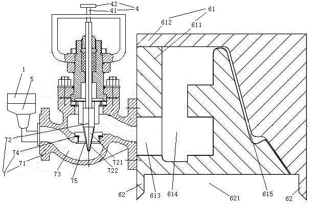
[0005] The invention provides a 3D printer nozzle structure capable of double-pass material spraying, which solves the problem that the existing 3D printer nozzles can only perform single-pass material spraying
When in use, the present invention is installed on the storage box in a manner of moving perpendicular to the length direction of the nozzle body. When the present invention moves back and forth (that is, two-way), the resin can be sprayed and filled into the storage box, and the scraper can immediately discharge the resin while discharging the resin. The upper surface of the resin is scraped flat, thus avoiding the problem of the resin layer being exposed to the air for a long time and being cured by ultraviolet rays, resulting in a decrease in fluidity

Method used


Image

  • 3D printer spray head structure
  • 3D printer spray head structure
  • 3D printer spray head structure

Examples


Embodiment 2

[0041] Embodiment two, the difference with embodiment one is:

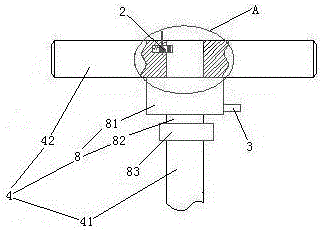
[0042] see image 3 , The opening and closing valve mechanism 4 also includes a motor 8 and a power switching mechanism 2 . The motor 8 includes a motor housing 81 and a motor shaft 82 . The motor housing 81 is fixedly connected with the grip bar 42 . The motor casing 81 is provided with the connection terminal 3 . The drive shaft 41 is connected to one end of the motor shaft 82 through a speed reducer 83 . The other end of the motor shaft 82 passes through the handle bar 42 .

[0043] see Figure 4 , The power switching mechanism 2 includes a switch 21 , a pressing rod 22 , a latch 23 and an insertion spring 24 . The switch 21 and the pressing rod 22 are located on both sides of the latch 23 . The switch 21 is fixed in the handle bar 42 . Switch 21 is a push switch, because the control motor 8 starts and stops. The pressing rod 22 passes through the grip rod 42 . The latch 23 is slidably connected in th...


PUM


Abstract

The invention relates to a printer, in particular to a 3D printer spray head structure. The 3D printer spray head structure comprises a spray head body, wherein a spray outlet and an inlet are formed in the spray head body; the spray head body is in a long strip shape; the spray outlet is a gap extending in the length direction of the spray head body; the spray head body is provided with two scraping knives; an expansion slot is formed between the two scraping knives; and the outlet end of the spray outlet is located in the expansion slot. The 3D printer spray head structure with a double way material spraying function is provided by the invention, and the problem that an existing 3D printer spray head can be used for conducting one way material spraying only is solved.

Description

technical field [0001] The invention relates to a printer, in particular to a nozzle structure of a 3D printer. Background technique [0002] A 3D printer is a device that prints based on the cumulative forming technology of the discrete accumulation principle. It integrates computer-aided design (CAD) and computer-aided manufacturing (CAM) with the help of modern means such as computer, laser, precision transmission and numerical control, and can directly manufacture products in a short time according to the three-dimensional model constructed on the computer. model or sample. [0003] There are many ways to form 3D printers. One of them is to use photosensitive resin as the raw material. The 3D model of the part designed on the computer is triangulated on the surface, stored in STL file format, and processed in layers to obtain the cross-section of each layer. The two-dimensional profile information, and then the computer controls the DLP projector to project the two-dim...

Claims


Application Information

Patent Timeline
Patent Type & Authority Applications(China)
IPC IPC(8): B29C67/00B33Y30/00
CPCB33Y30/00
Inventor 刘东升夏思东罗保宁陈健周翔刘春丽张红伟胡香玲郭天华
Owner HANGZHOU YANZHI SCI & TECH CO LTD
Learn More