Connecting rod clamping mechanism

The technology of a clamping mechanism and a connecting rod mechanism, which is applied in the field of clamping mechanism equipment, can solve the problems of increasing production cost, low clamping efficiency, time-consuming and labor-intensive, etc., and achieves the effects of high space utilization, simple and flexible structure, and high efficiency.

Active Publication Date: 2016-09-07
BOZHON PRECISION IND TECH CO LTD
View PDF6 Cites 18 Cited by
  • Summary
  • Abstract
  • Description
  • Claims
  • Application Information

AI Technical Summary

Problems solved by technology

[0002] The existing clamping mechanism generally uses a clamping jaw cylinder to drive a group of clamping jaws to move, and can only clamp one product at a time, and the clamping efficiency is low. Sometimes it is necessary to operate multiple groups of products at

Method used


Image

  • Connecting rod clamping mechanism
  • Connecting rod clamping mechanism
  • Connecting rod clamping mechanism

Examples


Embodiment Construction

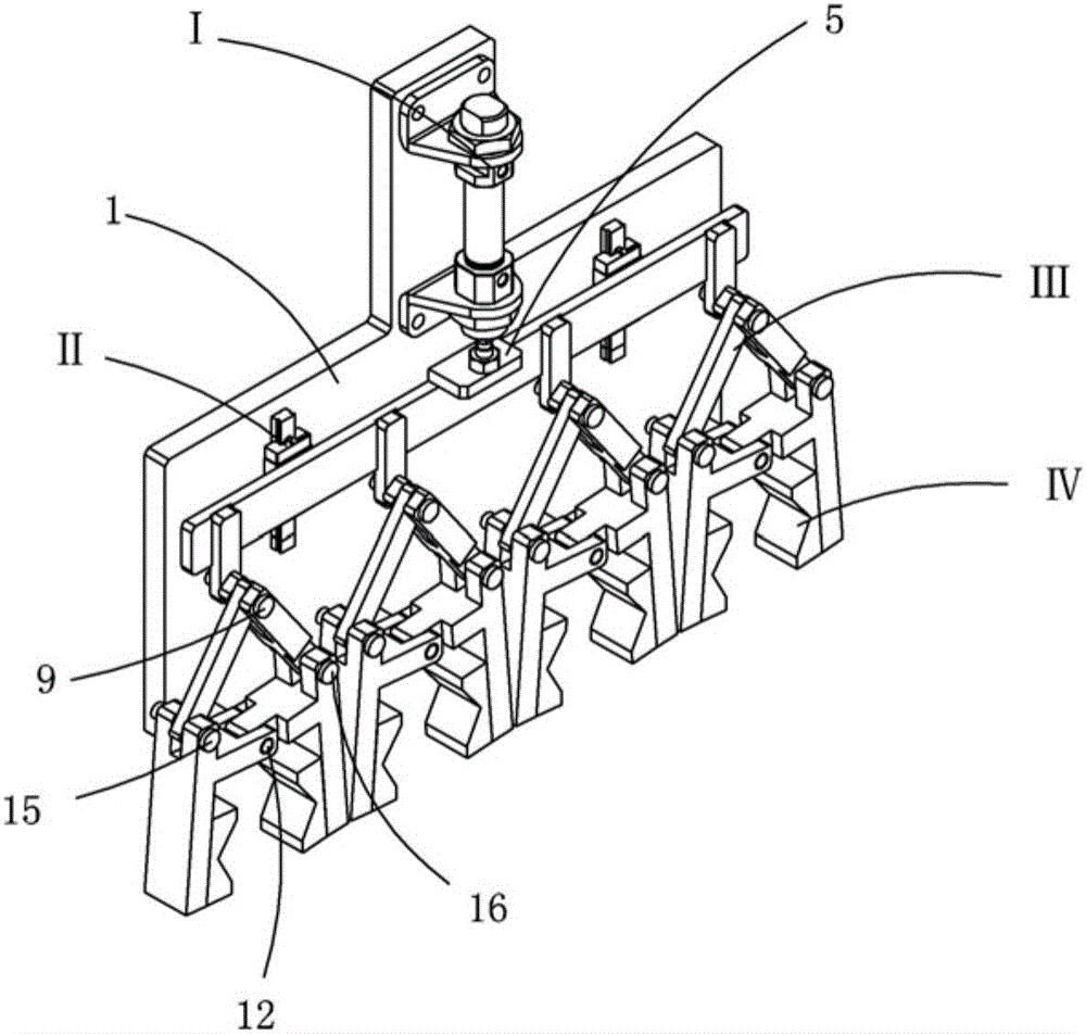
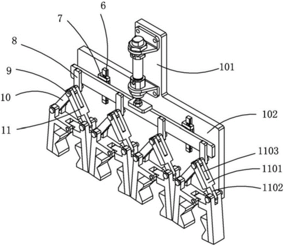
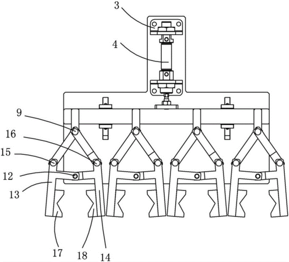
[0025] Examples, see attached Figure 1~6 , a connecting rod clamping mechanism, including a carrier plate 1 and a drive assembly I installed on the carrier plate, the lower end of the drive assembly is connected to a pull rod 2, and a guide assembly that guides the pull rod is installed on the carrier plate II; the lower end of the pull rod is connected with a linkage mechanism III, and the lower end of the linkage mechanism is equipped with a jaw assembly IV; the drive assembly drives the pull rod to move along the guide assembly, and under the action of the linkage mechanism, the clamp can be The jaw assembly clamps or loosens the product.

[0026] The carrier board is a convex structure, a driving assembly is installed on the small end 101 of the convex structure, and a guide assembly is installed on the large end 102 of the convex structure.

[0027] Four sets of linkage mechanisms are installed side by side at the lower ends of the pull rods, and a set of jaw assemblies...


PUM


Abstract

The invention relates to a connecting rod clamping mechanism. The mechanism comprises a loading board, and a driving assembly which is mounted on the loading board, wherein pulling rods are connected to the lower end of the driving assembly; guide assemblies for guiding the pulling rods are mounted on the loading board; connecting rod mechanisms are connected to the lower ends of the corresponding pulling rods; a clamping jaw assembly is mounted at the lower end of each connecting rod mechanism; the pulling rods can be driven by the driving assembly to move along the corresponding guide assemblies; a product can be clamped or released through the clamping jaw assemblies under the effect of the corresponding connecting rod mechanisms. The connecting rod clamping mechanism is simple and flexible in structure, and high in space utilization rate; a plurality of workpieces can be clamped through one powder source in one time, so that the efficiency is high, and the economy is increased; the connecting rod clamping mechanism is worthy of popularization and use in actual production.

Description

Technical field: [0001] The invention relates to the field of clamping mechanism equipment, and more specifically relates to a link clamping mechanism that only needs one power source and can clamp several workpieces at a time. Background technique: [0002] The existing clamping mechanism generally uses a clamping jaw cylinder to drive a group of clamping jaws to move, only one product can be clamped at a time, and the clamping efficiency is low. Sometimes multiple groups of products need to be operated at the same time on one station, so that one by one clamping It is time-consuming and labor-intensive, the working hours are long, and the production cost is also improved. Therefore, it is necessary to design a mechanism that can clamp several workpieces at a time. Invention content: [0003] The purpose of the present invention is to provide a connecting rod clamping mechanism aimed at the shortcomings of the prior art, which only needs one power source to clamp several ...

Claims


Application Information

Patent Timeline
IPC IPC(8): B65G47/90B25J15/10
CPCB25J15/106B65G47/901B65G47/907B65G2201/02
Inventor 吕绍林杨愉强王建福游伟
Owner BOZHON PRECISION IND TECH CO LTD
Why Eureka
Try Eureka