Cylindric pin with orientation correction for rough machining of lug

A cylindrical pin and lug technology, applied in the directions of shafts and bearings, mechanical equipment, pivots, etc., can solve the problems of time-consuming and laborious, the angle between the lugs and the lugs, and the increase in cost.

Active Publication Date: 2016-09-07
南通图海机械有限公司
View PDF5 Cites 1 Cited by
  • Summary
  • Abstract
  • Description
  • Claims
  • Application Information

AI Technical Summary

Problems solved by technology

[0002] At present, when lugs are generally installed, the first lug and the second lug are installed on the support of the lug. The angle between the first lug and the second lug is 0 degrees during normal installation. The master's immature technology often leads to abnormal installation. At this time, the angle between the lugs may appear between the lugs. If the traditional cylindrical pins are directly used, the installation position of the cylindrical pins may be shifted, resulting in the installation and fit on the cylindrical pins. The movement position of the structure deviates, causing the entire mechanical operation problem; often the solution is to further correct the installation position of the lug
The round holes on the other two lugs generally require the axes to coincide. If the axes of the round holes do not coincide, the lugs may need to be disassembled, resulting in increased costs and time-consuming and laborious situations.

Method used


Image

  • Cylindric pin with orientation correction for rough machining of lug
  • Cylindric pin with orientation correction for rough machining of lug
  • Cylindric pin with orientation correction for rough machining of lug

Examples


Embodiment Construction

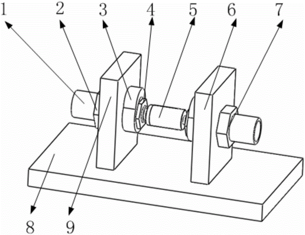
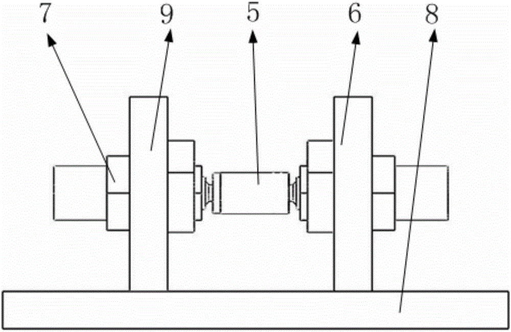
[0027] like figure 1 , 2 As shown, it includes cylindrical pin, first lug, lug support, second lug, and fixing mechanism, wherein the first lug and the second lug are installed side by side on the lug support, the first lug and the second lug Fixing mechanisms with exactly the same structure are installed on the lugs, and the cylindrical pin is installed between the two fixing mechanisms.

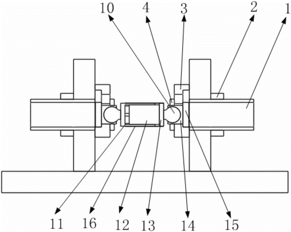
[0028] like image 3 As shown, the above-mentioned fixing mechanism includes a pillar, a first nut, an adjustment block, a second nut, a spherical shell, a spherical shell clamping plate, and a clamping plate supporting surface, wherein such as Figure 13 As shown, an adjustment block is installed at one end of the pillar, such as Figure 12 As shown, the adjustment block has a support surface on the side connected to the pillar, as shown in Figure 10 , 11 As shown, the spherical shell has a spherical inner cavity and the outer surface is a cylindrical surface with threads, and the sp...


PUM


Abstract

The invention belongs to the field of lug technology, and especially relates to a cylindric pin with orientation correction for rough machining of the lug. The cylindric pin comprises a straight pin, a first lug, a lug support, a second lug, fixing mechanisms, inner balls, ball cases, adjusting blocks, and the like; wherein the first lug and the second lug are installed on the lug support, the straight pin is installed on the first lug and the second lug by fixing mechanisms at double ends, the inner balls are installed at double ends of the straight pin, and the inner balls and the ball cases in the fixing mechanisms are matched for forming universal joints; the ball cases are installed on the adjusting blocks by ball case clamping plates; a second nut can steadily position the ball case on a certain position of the adjusting block, and fastening of a first nut can guarantee the fixing mechanism is steadily fixed on the lug. Furtherly, the straight pin has a nested structure of an externally covered rod and an inner rod, so that the length of the straight pin can be guaranteed according to self adjusting of a lug gap. The orientation of the cylindric pin can be adjusted according to installation position needs, and the cylindric pin has high practicality.

Description

Technical field [0001] The invention belongs to the technical field of lugs, and in particular relates to a straight pin with orientation correction for rough machining lugs. Background technique [0002] At present, when lugs are generally installed, the first lug and the second lug are installed on the support of the lug, and the angle between the first lug and the second lug is 0 degrees when the normal installation is performed. The master's immature technology often leads to abnormal installation. At this time, the angle between the lugs may appear between the lugs. If the traditional cylindrical pin is used directly, the installation position of the cylindrical pin may be shifted, resulting in the installation and fit on the cylindrical pin. The movement position of the structure deviates, causing the entire mechanical operation problem; often the solution is to further correct the installation position of the lug. The circular holes on the other two lugs generally re...

Claims


Application Information

Patent Timeline
IPC IPC(8): F16C11/06
CPCF16C11/0609
Inventor 柳超
Owner 南通图海机械有限公司
Why Eureka
Try Eureka