Blade structure for reducing noise and air loss of hydraulic retarder

A hydraulic retarder and blade structure technology, applied in the direction of liquid resistance brakes, brake components, noise/vibration control, etc., can solve the noise problems of vehicle drivers and residents around the road, increase vehicle fuel consumption, energy loss, etc. problem, to achieve the effect of improving driving safety, reducing interference and reducing noise

Pending Publication Date: 2021-10-29
TRANSPOWER HYDRAULIC ENG XIAN
View PDF0 Cites 0 Cited by
  • Summary
  • Abstract
  • Description
  • Claims
  • Application Information

AI Technical Summary

Problems solved by technology

[0002] In recent years, hydraulic retarders are gradually being widely used in the field of road transport vehicles, passenger cars and mining vehicles, and with the rapid development of social economy, noise pollution is getting more and more attention, but the hydraulic retarder is working , to feed compressed air into the oil pool shell, so that the oil enters the working chamber and is agitated at high speed, which will generate a lot of noise; at the same time, the input end of the hydraulic retarder and the output end of the gearbox are in a constant meshing state. During the process, due to the meshing transmission of the gears, the rotor of the hydraulic retarder has been rotating at a high speed, which will cause energy loss during normal driving and climbing, and increase the fuel consumption of the vehicle.
[0003] At present, there is no good solution to the noise of the hydraulic retarder under the action of the blades of the stator and rotor. The noise value of the hydraulic retarder under the maximum braking torque condition exceeds 120dB, which is harmful to the vehicle driver and the road. The surrounding residents have brought a lot of noise troubles, which has a negative effect on the construction and development of a green and environmentally friendly society. For this reason, we propose a blade structure that reduces the noise and air loss of the hydraulic retarder.

Method used


Image

  • Blade structure for reducing noise and air loss of hydraulic retarder
  • Blade structure for reducing noise and air loss of hydraulic retarder
  • Blade structure for reducing noise and air loss of hydraulic retarder

Examples


Embodiment 1

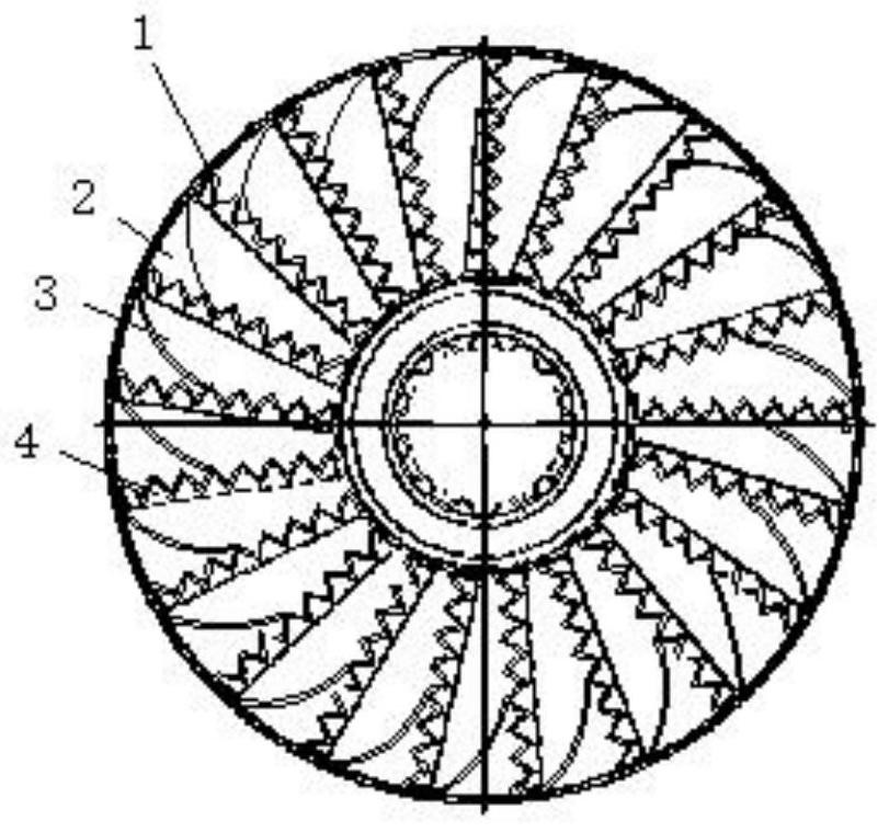
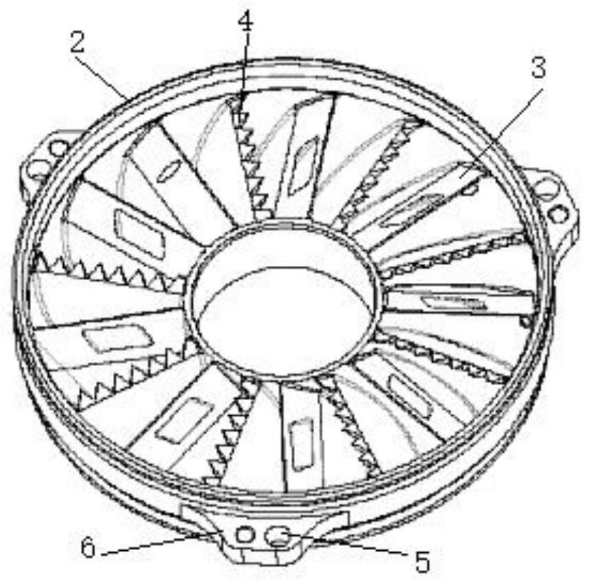
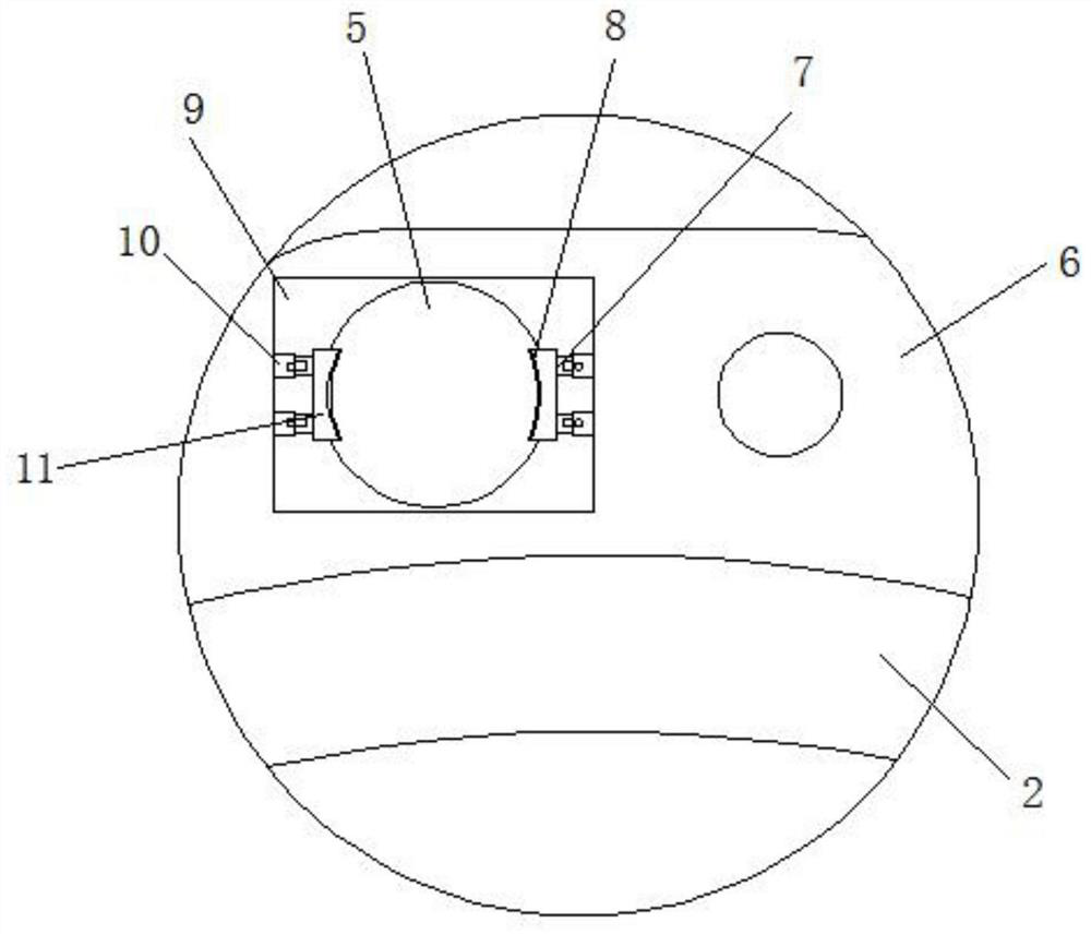
[0022] see Figure 1 to Figure 5 , the present invention provides a technical solution: a blade structure for reducing noise and air loss of a hydraulic retarder, including a stator 1 and a rotor 2, the stator 1 is located on one side of the rotor 2, and the inner side of the stator 1 and the rotor 2 is provided with The blades 3, the blades 3 in the stator 1 and the rotor 2 are all arranged in a circular array, and the edge of one end of the blade 3 is fixed with a saw-toothed bar 4, and the designed saw-toothed bar 4 is installed on the blade 3, thereby realizing the Changing the tooth shape of rotor 2 and stator 1 has the effect of reducing noise and drag. There are tooth grooves on the sawtooth bar 4, and the tooth grooves are located on the sawtooth bar 4 in a half-sine wave. The cogging on the top is set with sine wave fluctuations, thereby ensuring that the sawtooth bar 4 changes the eddy current intensity in the working chamber of the rotor 2 and the stator 1, which ca...

Embodiment 2

[0026] see Figure 1 to Figure 5 , the present invention provides a technical solution: a blade structure for reducing noise and air loss of a hydraulic retarder, including a stator 1 and a rotor 2, the stator 1 is located on one side of the rotor 2, and the inner side of the stator 1 and the rotor 2 is provided with The blades 3, the blades 3 in the stator 1 and the rotor 2 are all arranged in a circular array, and the edge of one end of the blade 3 is fixed with a saw-toothed bar 4, and the designed saw-toothed bar 4 is installed on the blade 3, thereby realizing the Changing the tooth shape of rotor 2 and stator 1 has the effect of reducing noise and drag. There are tooth grooves on the sawtooth bar 4, and the tooth grooves are located on the sawtooth bar 4 in a half-sine wave. The cogging on the top is set with sine wave fluctuations, thereby ensuring that the sawtooth bar 4 changes the eddy current intensity in the working chamber of the rotor 2 and the stator 1, which ca...

Embodiment 3

[0030] see Figure 1 to Figure 5, the present invention provides a technical solution: a blade structure for reducing noise and air loss of a hydraulic retarder, including a stator 1 and a rotor 2, the stator 1 is located on one side of the rotor 2, and the inner side of the stator 1 and the rotor 2 is provided with The blades 3, the blades 3 in the stator 1 and the rotor 2 are all arranged in a circular array, and the edge of one end of the blade 3 is fixed with a saw-toothed bar 4, and the designed saw-toothed bar 4 is installed on the blade 3, thereby realizing the Changing the tooth shape of rotor 2 and stator 1 has the effect of reducing noise and drag. There are tooth grooves on the sawtooth bar 4, and the tooth grooves are located on the sawtooth bar 4 in a half-sine wave. The cogging on the top is set with sine wave fluctuations, thereby ensuring that the sawtooth bar 4 changes the eddy current intensity in the working chamber of the rotor 2 and the stator 1, which can...


PUM


Abstract

The invention discloses a blade structure for reducing noise and air loss of a hydrodynamic retarder. The blade structure comprises a stator and a rotor, the stator is positioned at one side of the rotor, blades are arranged at the inner sides of the stator and the rotor, the blades in the stator and the rotor are arranged in a circular array, a sawtooth strip is fixed at the edge of one end of each blade, and a tooth groove is formed in each sawtooth strip. According to the blade structure, the designed sawtooth strips are mounted on the blades, so that the effect of reducing noise and resistance is achieved by changing the tooth shapes of the blades of the rotor and the stator; and the designed tooth grooves in the sawtooth strips are arranged in a sine wave fluctuation manner, so that the sawtooth strips are ensured to change the vortex intensity in working cavities of the rotor and the stator, the noise of the hydraulic retarder can be effectively reduced, interference of the noise of the hydraulic retarder to a driver is reduced, the driving safety is improved, noise pollution to the surrounding environment is reduced, and good social benefits are achieved.

Description

technical field [0001] The invention belongs to the technical field of hydraulic retarders, and in particular relates to a blade structure for reducing the noise and air loss of the hydraulic retarder. Background technique [0002] In recent years, hydraulic retarders are gradually being widely used in the field of road transport vehicles, passenger cars and mining vehicles, and with the rapid development of social economy, noise pollution is getting more and more attention, but the hydraulic retarder is working , to feed compressed air into the oil pool shell, so that the oil enters the working chamber and is agitated at high speed, which will generate a lot of noise; at the same time, the input end of the hydraulic retarder and the output end of the gearbox are in a constant meshing state. During the process, due to the meshing transmission of the gears, the rotor of the hydraulic retarder has been rotating at a high speed, which will cause energy loss during normal drivin...

Claims


Application Information

Patent Timeline
IPC IPC(8): F16D57/02F16D65/00
CPCF16D57/02F16D65/0006
Inventor 赵鑫赵小宇殷楠赵甜甜
Owner TRANSPOWER HYDRAULIC ENG XIAN
Why Eureka
Try Eureka