Water softener control valve and control method thereof

A technology for controlling valves and water softeners, which is applied in water treatment parameter control, chemical instruments and methods, and valve operation/release devices, etc. It can solve the complex flow path inside the valve body, affect the life of the soft water valve, and design difficulties for planar valves, etc. problems, to achieve the effect of simple structure, good regeneration effect and water saving

Active Publication Date: 2016-09-07
XIAMEN BAILIN WATER PURIFICATION TECH CO LTD
View PDF10 Cites 14 Cited by
  • Summary
  • Abstract
  • Description
  • Claims
  • Application Information

AI Technical Summary

Problems solved by technology

However, due to the difficulty in the design of the planar valve, the number of holes in the valve plate of the planar valve is relatively large, which makes the internal flow path of the valve body complicated; second, in the softening process of the fixed bed, the regeneration of salt absorption is usually downstream regeneration, The downstream regeneration means that the brine flows downward from the upper part of the resin layer, and the brine cannot fully contact with the resin layer, which consumes a lot of water; third, the existing water softener uses two valves, which is difficult to realize within one rotation of the moving valve. Realize the five major functions of softening, backwashing, downstream or countercurrent salt absorption regeneration, positive washing, and water replenishment in sequence. If they cannot be realized in sequence, the soft water valve will have to turn back and forth several times in order to realize a regeneration process flow, which will affect the soft water. valve life

Method used


Image

  • Water softener control valve and control method thereof
  • Water softener control valve and control method thereof
  • Water softener control valve and control method thereof

Examples


Embodiment Construction

[0039] In order to make the above-mentioned features and advantages of the present invention more comprehensible, the following specific embodiments are described in detail with reference to the accompanying drawings, but the present invention is not limited thereto.

[0040] refer to Figure 1 to Figure 16

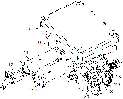
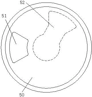
[0041] A water softener control valve, comprising a valve body 10, the valve body is provided with a water inlet 11, a water outlet 12, a sewage outlet 13, a filter element outer interface 14, a filter element inner interface 15 and a salt suction port 16, and the valve body is provided with a useful In the injector inlet 17 and the injector outlet 18 connected with the injector 20, and the electromagnetic valve inlet and the electromagnetic valve outlet used to be connected with the solenoid valve 30, a fixed valve plate 40 is also arranged in the valve body and driven by The movable valve plate 50 driven by the mechanism, the first to sixth through holes 41, 42, 43, 44...


PUM


Abstract

The invention relates to a water softener control valve and a control method of the water softener control valve. The water softener control valve comprises a control body. A water inlet, a water outlet, a sewage drainage opening, an outer filter element connector, an inner filter element connector and a salt suction opening. An ejector inlet, an ejector outlet, a magnetic valve inlet and a magnetic valve outlet are formed in the valve body, the ejector inlet and the ejector outlet are used for being connected with an ejector, and the magnetic valve inlet and the magnetic valve outlet are used for being connected with a magnetic valve. A fixed valve block and a movable valve block driven by a drive mechanism are also arranged in the valve body. A first through hole, a second through hole, a third through hole, a fourth through hole, a fifth through hole and a sixth through hole are formed in the periphery of the fixed valve block at intervals. A seventh through hole communicating with the sewage drainage opening is formed in the middle of the fixed valve block. The first through hole, the fourth through hole and the sixth through hole communicate with the outer filter element connector. The second through hole communicates with the inner filter element connector, the water outlet and the magnetic valve. The third through hole communicates with the salt suction opening and the ejector inlet. The fifth through hole is sealed. A water inlet hole and a breakover blind hole are formed in the periphery of the movable valve block. The water softener control valve is compact in structure and can achieve automatic switching of states of a water softener, and the control method is easy and convenient to implement.

Description

technical field [0001] The invention relates to a water softener control valve and a control method thereof. Background technique [0002] In water treatment applications, multi-functional soft water valves are often used to achieve functions such as softening, backwashing, salt absorption regeneration, positive washing, and water replenishment. Due to its simple structure and high reliability, the planar sealing multi-way valve has gradually become one of the main valve types in the field of multi-function control valves in recent years. However, due to the difficulty in the design of the planar valve, the number of holes in the valve plate of the planar valve is relatively large, which makes the internal flow path of the valve body complicated; second, in the softening process of the fixed bed, the regeneration of salt absorption is usually downstream regeneration, The downstream regeneration means that the brine flows downward from the upper part of the resin layer, and ...

Claims


Application Information

Patent Timeline
Patent Type & Authority Applications(China)
IPC IPC(8): F16K11/074F16K31/04F16K31/53C02F5/00C02F103/02
CPCC02F5/00C02F2103/02F16K11/074F16K31/042F16K31/535C02F1/42C02F2001/425C02F2201/005C02F2303/16F16K37/0041C02F2101/10C02F2209/00C02F2303/22F16K3/029F16K31/043
Inventor 詹丰顺连宇炜
Owner XIAMEN BAILIN WATER PURIFICATION TECH CO LTD
Why Eureka
Try Eureka